Architecture details and discussions archive
- Guillaume Lambert
YANG models used in TransportPCE
East/West APIs YANG models
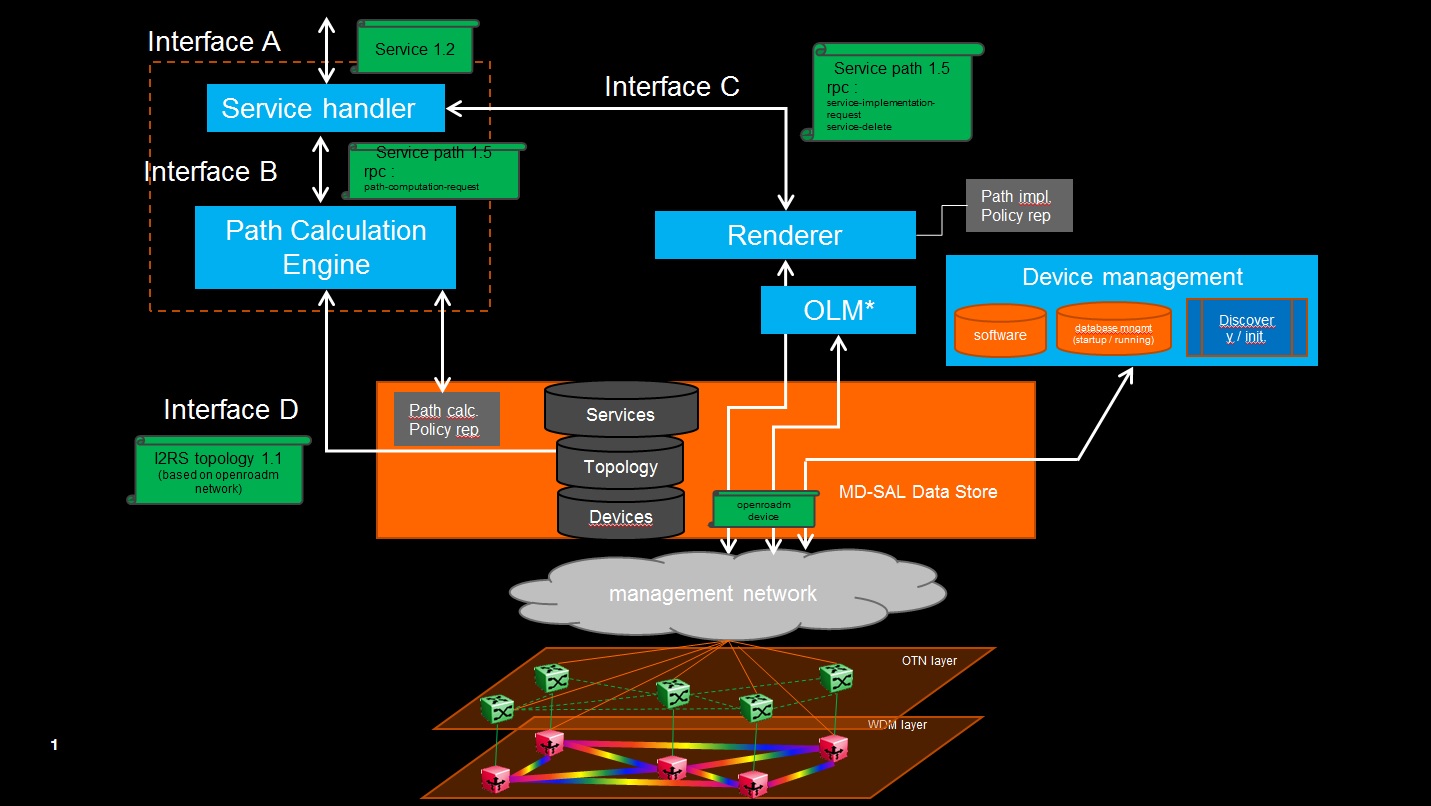
Transport PCE is based on a modular structure. Some of the bundles are tightly connected to the type of equipment handled by the controller. This is the case of the Renderer and the OLM that allow configuring OpenROADM equipment. Thus the algorithms of the different functions they implement, respect the procedure defined in the OpenROADM Device white paper.
Some other modules are less tightly coupled to the type of controlled equipment, such as the PCE and the Topology discovery. To ease further evolution Transport PCE specific models are published on the following Github repository: https://github.com/transportPCE/transportPCE_Public
Published models define a common base allowing the different modules to share the information present in the DataStore and to communicate. They can be used as a reference by contributors to develop complementary/additional features. These new features as far as they rely on the reference model could be triggered from existing module, in place of others having the same functionality for different kind of equipment, or to complement existing functions.
As an example we could imagine extending the support of equipment following different models. This would imply to develop some specific OLM & Renderer to configure the devices and to extend the topology model through additional augmentations.
OpenROADM YANG models
Overview
OpenROADM Device and Network Models have been presented by AT&T: Open_ROADM_Models_v0_2.pdf
Full models can be retrieved following OpenROADM website (download section).
Initial Discussion around RFC 7446
Orange (XP) review- Aditional review by other contributors is welcome.
Static information
Connectivity matrix
Section 4.1 specifies a connectivity matrix indicating which input port could possibly be connected to which output port. This is similar to the connectivity-map in openroadm network model with still some differences in presenting data.ressource pool
As far as I understand this part, it is related to regenerators or wavelength converters. As far as Orange is concerned, these functions are not taken into consideration in ROADM modeling. If regeneration is needed/preferred, it is up to the PCE to decide where to make it taking into consideration ROADM, transponders, and OTN switches. One could say that two transponders back to back become a regen/converter, but the two transponders can also be used without being back to back. Therefore, it seems to me more adquate to have the granularity of transponder and let the PCE decide whether associating 2 of them or not.Link information
This part is fundamental for PCE and shall be described in the link part of I2RS model structure. As far as OTN/WDM are concerned, links can either be OTUx or LO-ODUx. Most of the information described in section 6 is relevant. Port label restrictions are still vague to me.Dynamic information
Agreed with dynamic link information even if bandwidth (for LO-ODU) should be added. For node information, it is related to resource pool and therefore probably not relevant.Synthesis
Information related to links shall be modeled in the link part of I2RS model structure and there is no real reason for diverging with RFC 7446. It will however enriched with additional information in order to perform accurate path feasibility calculation or to ensure some service metrics are checked. Regarding node description, I am not sure to see how they can really converge. One model is de-aggregated for accurate path calculation (typically for disjointness requirements) while it may be diificult to derive one de-aggregated from RFC 7446. Besides, the notion of resource pool does probably not meet the needs for the reason given here above (transponder can be used for regen or not).
Ericsson (FL) commentActually, resource pool is a more complex and general concept, as it's a modular and versatile blocks based approach. Its aim is to model any connectivity limitation inside a node, and is applicable not only to ROADMs, but also to other technologies, typically to model connectivity limitations of multiple technologies NEs, like a NE having both OTN and WDM switching capabilities (e.g. Ericsson SPO family has exactly this capabilities, and also allows to add SDH and packet switching altogether).
When some ports can be connected with a subset of the other ports available inside the NE, and possibly the guaranteed connectivity has also limitations (e.g. there is a limit on the maximum switchable bandwidth) this model can be very useful.
Besides, resource pool is not limited to regeneration and wavelength conversion. There are other cases where this is useful :
- Modeling of transponders "add/drop" of a single line (fixed connectivity to the relevant line only)
- Modeling of transponder sharing mechanisms (connectivity to an intermediate stage allowing directionless/colorless/contentionless routing). Occupation of the intermediate sharing hardware must also be taken into account when assigning or verifying lambdas.
The intermediate sharing stage can be in turn connected to all or part of the line interfaces of the NE, and once again this can be done effectively with the resource pool mechanism.
- Lambda limitations on internal HW (beside the case highlighted at the previous point); e.g. lambda limitations due to transponder ports, filters or other equipment configured on the NE.
Resource pool concept is based on two types of objects:
- Resource blocks, representing a general set of internal NE resources, and keeping track of their capabilities, occupation and relationship with external interfaces (the traffic ports of the NE)
- Connectivity matrixes, representing actual connectivity between resource blocks.
This way it's possible in a very comprehensive and detailed way to model the internal structure of a generic NE with its real limitations, taking into account their current usage.
I understand that the other model is more focused on WDM NEs, and possibly less general. Deciding whether to use one of the other would require to do a more detailed use case analysis, taking into account real NE scenarios, not only in WDM domain but also in OTN (at least) as this is an additional target of the project.
From OpenROADM network model to an I2RS compatible topology description
The I2RS draft version (4) can be retrieved at https://tools.ietf.org/html/draft-ietf-i2rs-yang-network-topo-04

Modules description
Path Computation Engine/Element
PCE description
The Path Computation Element (PCE) is the component inside TransportPCE project responsible for path computation. An interface allows other components of the TransportPCE to request a path computation and get a response from the PCE including the computed path(s) in case of success, or errors and indication of the reason for the failure in case the request cannot be satisfied. Additional parameters can be provided by the PCE in addition to the computed paths if requested by the client module. Additional interfaces allow to keep PCE aligned regarding topology and traffic deployed in the network.
PCE implementation
PceConstraintsCalc class parses constraints calling calcHardConstraints and readConstraints methods and saves them for a quick use. Open ROADM service model defines both soft and hard constraints. Only hard constraints are considered in current implementation. Routing constraints handled are the following:
- General constraints: exclude Node/SRLG, maximum latency
- Diversity constraints: with respect to the path(s) of a specific service or a list of service
Co-routing constraints are not handled at this stage. The exclusion of Diversity constraints is handled in 2 steps. readDiversityNodes recovers the path description(s) of the service or the service list from the Service-path DataStore. From the path description, getAtoZNodeList extracts the nodes and converts the diversity constraint to a general node exclusion constraint.
PceCalculation is dedicated to the topology analysis and pruning before the path computation is launched. It performs this in 2 steps relying on the following 2 main methods:
- readMdSal : Reads the topology layer of the Open ROADM Network topology built in the MD-SAL by the Topology Management module. This layer includes the disagregated nodes (SRGs, Degrees, Xponders) as well as the links between these nodes.
- analyzeNW : minimizes the amount of nodes/links extracted from the topology to use in the graph according to the arguments of the PCE request. From all the nodes present in the initial topology, validateNode removes all Xponder nodes that do not correspond to A or Z end of the demand, as well as all the Nodes that correspond to a hard exclude constraint through validateNodeConstraints.
 Network Analyzer logic
PceGraph class is dedicated to the path calculation. Current solution in a first step populates graph with relevant nodes (degrees, SRGs, Xponders) and links from the pruned topology using populateGraph method.
In a second step, it relies on CalcPath which calculates the path according to 2 tracks. In the fast track it attempts to calculate the path calling runGraph and indirectly calcAlgo methods which returns a Dijkstra Shortest path according to the selected metric. Currently supported metrics are hop-count and propagation-delay. Graph algorithm finds K shortest AtoZ paths. chooseWavelength method checks that a wavelength continuity can be found for the returned paths. The first (best) AtoZ path with single wavelength is chosen. ZtoA path is derived from AtoZ.
If no wavelength continuity can be provided for the shortest path, a second track is explored. Before populating the graph, extractWLs extracts the list of available wavelengths for each node of the pruned topology, and for each wavelength creates a list of the nodes for which this wavelength is available. The path calculation is still performed calling runGraph and calcAlgo methods, this time scanning all the wavelength on a topology which considers wavelength availability.
PceLink and PceNode create objects with all the attributes needed for pathcalculation. PceLink includes methods to retrieve the link-type, the associated opposite-link, the latency and the source and destination tps. PceNode includes the methods to retrieve available wavelengths, client tails and outgoing links.
PceSendingPceRPCs defines all methods required to handle the RPCs associated with Path computation and the cancellation of resource reservation. This includes the error handling and the construction of the output of rpc with the response codes and the path-description when required. The main methods defined in this Class are :
- cancelResouceReserve :
- pathComputation : first launches constraint calculation from hard and soft constraints contains in the input of path-computation-request rpc. In a second step reads and analyse the topology (PceCalculation readMdSal and analyseNW). In a third step launches the graph and the path calculation (Graph calcPath). In case path calculation based on hop-count metric (by default) fails because path's latency exceeds the defined constraint, changes the metric to propagation-delay and launches a new path calculation using the following method.
- patchRerunGraph : launches the graph and the path calculation (Graph calcPath) after the metric was changed to propagation-delay.
PcePathDescription is the class used to build the path-description returned in the output of the path-computation-request rpc and the service-path-rpc-result notification. This path description is built as a succession of SourceTp & (SouceNode)-Node-tp-link-tp-Node....link-tp-DestinationTp & DestinationNode.
PathComputationServiceImpl defines the handling of path-computation-request and cancel-resource-reserve RPCs, overriding the 2 corresponding methods defined in the PathComputationService interface. It computes the messages of the output of the rpcs according to the context and the result obtained through the path calculation. It also handles notification service-path-rpc-result providing the status of the path calculation (pending, successful, failed).
PCE initial requirements
The following table describes the requirements for the PCE module. The scope is limited to the path computation related operations, as the topology is covered by another section of the TransportPCE project.
The columns of the table are :
- Id - an identifier of the requirement. The idea is to use a structured identifier in order to build a hierarchy of requirements; see the table below
- Slogan - a short title of the requirement
- Description - a detailed description of the requirement
- Reference - If the requirement is derived from or refers to an external document (e.g. an IETF RFC or draft) this column includes the relevant information
- Priority - The priority of the requirement as agreed between the TransportPCE contributors. Here we propose a simple number like 1 = Mandatory requirement and increasing numbers to indicate lower priority or optional requirements. Range of values to be decided.
Proposed range: 1 = Mandatory 2 = Second priority 3 = Nice to have
- Agreed - A "Yes" in this columns means that the requirement is agreed among the contributors and therefore is a valid requirement for the project.
- Comments - Comments from TransportPCE contributors
| Id | Slogan | Description | Reference | Priority | Agreed | Comments |
|---|---|---|---|---|---|---|
| 1 | Architecture and Interfaces | |||||
| 1.1 | RESTconf API | The PCE shall use a RESTconf API to provide path computation services to its clients | not agreed | Discussion ongoing. Orange: requirement becomes probably irrelevant if we talk about interface with service handler since both function will be colocated. PCEP or another API with similar data model is probably fine. | ||
| 1.2 | Capability to modify path feasibility verification algorithm | Path feasibility function shall be easily accessible for modification | [E///]P1 [Telia]P1 [Orange]P1 [Coriant]P1 | R1 | Keeping the topology model unchanged, an operator may want to improve the path feasibility algorithm with its own one for typically longer reach calculations [Coriant]or to include validation of equipment switching capabilities/restrictions. Therefore, this function must be easibily identified and modified if need be. Discussion ongoing | |
| 1.3 | Statefulness | PCE must be stateful. This means that it, besides topology, stores all the information related to the existing paths and is capable to use them for path computation, as needed | draft-ietf-pce-stateful-pce-15 | [E///]P1 [Telia]P1 [Orange]P1 [Coriant]P1 [Nokia] P1 | R1 | Discussion ongoing |
| 1.4 | Path information management | PCE stores and manages information about the paths deployed in the network, allowing to add, modify and remove that information | draft-ietf-pce-stateful-pce-15 | [E///]P1 [Telia]P1 [Orange]P1 [Coriant]P1 | R1 | Please note that PCE should NOT store path information and mark network resources as in use at the moment of successful path computation. The client application shall be instead in charge of deploying the path and eventually update the PCE |
| 1.5 | path identification | PCE must manage unique identifier associated to each path. This id must be assigned by the client, is under client’s responsibility and must remain constant across all the life of the path | [E///]P1 [Telia]P1 [Orange]P1 [Coriant]P1 [Nokia] P2 | R1 | ||
| 1.6 | Multi-layer path computation | PCE must support multi-layer (and multi-technology) path computation. This means that a multi-layer/multi-technology network may be represented in its topology database, and path computation can return multi-layer/multi-technology paths, that is paths whose route includes hops from different layers/technologies | [E///]P1 [Telia]P1 [Orange]P2 [Coriant]P1 [Nokia] P2 | R2 | Orange: P2 simply because OTN will come with release 2 of openroadm and first release will probably focus on WDM but will have to be multi-layer in the end for sure. | |
| 1.6.1 | DWDM switching support | PCE must manage DWDM technology | [E///]P1 [Telia]P1 [Orange]P1 [Coriant]P1 [Nokia] P1 | R1 | ||
| 1.6.2 | OTN switching support | PCE must manage OTN technology | [E///]P1 [Telia]? [Orange]P2 [Coriant]P1 [Nokia] P2 | R2 | Orange: for the reason above. OTN in PE to come not earlier than openroadm | |
| 1.6.3 | Mixed-technology networks : OTN/DWDM | OTN over photonic layering must be supported | [E///]P1 [Telia]P1 [Orange]P2 [Coriant]P1 [Nokia] P2 | R2 | Discussion ongoing | |
| 1.7 | Topology database | PCE get updates about the topology from the topology DB of the controller [Coriant], including nodes, ports and links availability | [E///]P1 [Orange]P1 [Coriant]P1 [Nokia] P1 | R1 | Discussion ongoing | |
| 1.8 | MD-SAL API | The PCE shall be provided as an ODL bundle, supporting MD-SAL API | [E///]P1 [Telia]P1 [Orange]P1 [Coriant]P1 | R1 | Orange: OK with ODL bundle. Not sure about MD-SAL API. PCE resides in network services, not in MD-SAL, correct? And REST API is important for Service handler. | |
| 1.9 | PCE tracing and debugging | The PCE shall provide a tracing facility where it shall be possible to have details about the path computation operations | [E///]P2 [Telia]P3 [Orange]P1 [Nokia] P3 | R2 | Orange: useful to understand PCE behavior | |
| 1.10 | PCE monitoring and performance measurements | The PCE supports measurements of performances, keeping track of the number of requests, minimum, maximum and medium time for the path computation operations | RFC 5886 | [E///]P2 [Telia]P2 [Orange]P3 [Coriant]P3 [Nokia] P3 | R2 | |
| 2 | Request Parameters | |||||
| 2.1 | Single path path computation | PCE must support the computation of a single path | RFC 5440 | [E///]P1 [Telia]P1 [Orange]P1 [Coriant]P1 [Nokia] P1 | R1 | |
| 2.2 | Single path optimization | PCE must support the optimization of a single path. The optimization shall compute an alternative path with a better metric allowing the reuse of resources allocated to the original path | RFC 5440 | [E///]P2 [Telia]P2 [Orange]P2 [Coriant]P2 [Nokia] P3 | R2 | |
| 2.3 | Multiple path path computation for diversity | PCE must support the computation (or optimization) of a bundle of paths, according to the wanted diversity, meaning that PCE shall be capable to compute multiple paths in diversity each other. Diversity attributes are defined as Node, Link, or SRLG. | RFC 5440 | [E///]P1 [Telia]P2 [Orange]P1 [Coriant]P2 [Nokia] P1 | R1 | Orange: SRG (add-drop group) should also be included in the list of diversity attributes |
| 2.4 | Multiple path path computation for global optimization | PCE must support the computation (or optimization) of a bundle of paths, according to objective functions | RFC 5441 RFC 5557 | [E///]P3 [Telia]P3 [Orange]P3 [Coriant]P3 [Nokia] P3 | R3 | |
| 2.5 | Multiple path path computation for computing multiple paths assigning separate resources | PCE must support the computation of multiple paths without any cross-path constraint. In this case the multiple paths shall be assigned different non-overlapping resources | RFC 5440 | [E///]P2 [Telia]P3 [Orange]P3 [Coriant]P3 [Nokia] P3 | R3 | |
| 2.6 | Constrained path computation | PCE must support the specification of multiple optional parameters to specify constraints for the path computation (or optimization). A flag must be included for each one of these parameters in order to specify whether the PCE will return failure or not when the relevant constraint cannot be satisfied. | RFC 5440 | [E///]P1 [Telia]P2 [Orange]P1 [Coriant]P2 | R1 | Discussion ongoing |
| 2.7 | Path computation result | PCE must be capable to return the result of the path computation (success, failure) | RFC 5440 | [E///]P1 [Telia]P1 [Orange]P1 [Coriant]P1 [Nokia] P1 | R1 | |
| 2.8 | Path computation result : unsatisfied constraints | In case not all the requested constraints can be satisfied, the PCE must report the unsatisfied ones | RFC 5440 | [E///]P1 [Telia]P1 [Orange]P1 [Coriant]P2 [Nokia] P3 | R1 | [Coriant] It would be useful also to be able to specify soft and hard constraints and support the auto relaxation of soft constraints [E///] See requirement 2.6 |
| 2.9 | Bidirectional path computation | PCE must support the computation (or optimization) of point-to-point bidirectional paths | RFC 5440 | [E///]P1 [Telia]P1 [Orange]P1 [Coriant]P1 [Nokia] P1 | R1 | |
| 2.10 | Unidirectional path computation | PCE must support the computation (or optimization) of point-to-point unidirectional paths | RFC 5440 | [E///]P3 [Telia]P3 [Orange]P3 [Coriant]P3 [Nokia] P3 | R3 | Discussion ongoing |
| 2.11 | End points | The request shall include the end points of the path to be computed. End-point information must include at least the specification of the node or interface of the end-point and optionally (depending on the technology of the network) unnumbered interface id and Label | RFC 5440 | [E///]P1 [Telia]P1 [Orange]P1 [Coriant]P1 [Nokia] P1 | R1 | Discussion ongoing |
| 2.11.1 | End points | The request shall include the clli without node / port information. It is up to the PCE to select the most appropriate resource at the edges.l | RFC 5440 | [Orange]P2 [Coriant]P1 [E///]P2 | R2 | Comes from discussion 2.11. Discussion ongoing |
| 2.12 | Bandwidth/Type of signal specification | PCE must allow specifying the bandwidth of the requested path.Bandwidth specification shall include the type of the signal (according to the technology type) | RFC 5440 | [E///]P1 [Telia]P1 [Orange]P1 [Coriant]P1 | R1 | Discussion ongoing |
| 2.13 | Metrics for path computation | PCE must allow specifying the metric to be optimized when performing path computation. Possible metrics are at least IGP metric, TE metric, Hop count, and propagation delay (latency). If no metric is specified, the IGP metric (administrative cost) shall be used by default. Additional constraints due to technology (e.g. optical path feasibility) may be implicitly considered by the PCE as needed | RFC 5440 | [E///]P1 [Telia]P1 [Orange]P1 [Coriant]P1 [Nokia] P1 | R1 | Discussion ongoing |
| 2.14 | Metric bound constraint | PCE must allow specifying the upper bound for a given metric (possibly a metric different from the one to be optimized). If no path with the given metric under the upper bound is found, the request must fail | RFC 5440 | [E///]P1 [Telia]P2 [Orange]P2 [Coriant]P2 [Nokia] P2 | R1 | |
| 2.15 | Computed metric returned as result | PCE must allow specifying the metrics to be returned for the computed path, as successful. In that case the relevant metrics of the computed path shall be included in the response. No metric is returned if not requested | RFC 5440 | [E///]P2 [Telia]P2 [Orange]P1 [Coriant]P2 [Nokia] P3 | R2 | |
| 2.16 | Use of local protected links in path computation | PCE must allow specifying whether the path computation shall use locally protected links | RFC 5440 | [E///]P3 [Telia]P2 [Orange]P2 [Coriant]P2 [Nokia] P3 | R2 | [Coriant] I think it is more than just locally protected links since it possible to use SNC type protection as end-to-end resiliency mechanism. Ideally, the different protection mechanisms available on the optical layer (DWDM/OTN) should be available and selected based on a requested parameter |
| 2.17 | Affinities | PCE allows specifying the affinities to be included or excluded by the path computation. Affinities (aka administrative colors) are coded as 32 bit masks. They are attributes of TE-links. It must be possible to specify the following conditions; Include-any: links are included if any of the bits set in the mask are set also in the relevant link affinities; Exclude-any: links are excluded if any of the bits set in the mask are set also in the relevant link affinities; Exclude-all: links are excluded if all the bits set in the mask are set also in the relevant link affinities | RFC 5440 | [E///]P1 [Telia]P1 [Orange]P1 [Nokia] P2 | R1 | Discussion ongoing |
| 2.18 | Include resources specification | PCE allows specifying the IRO, which is the list of network resources (nodes, links, interfaces) to be included in the computed path. The resulting path must pass through the elements in the IRO list according to their order. | RFC 5440 | [E///]P2 [Telia]P2 [Orange]P1 [Coriant]P2 [Nokia] P2 | R2 | |
| 2.19 | Exclude resources specification | PCE must allow specifying the XRO, which is the list of network resources (nodes, links, interfaces, SRLGs), to be excluded by the computed path. The resulting path must not pass through the elements in the list. | RFC 5521 | [E///]P1 [Telia]P1 [Orange]P1 [Coriant]P2 [Nokia] P1 | R1 | |
| 2.20 | Path profiles | PCE supports path profiles, that is specifications of set of request parameters and policies bundled all together and associated to a unique identifier. Mentioning that identifier in a request allows getting all the relevant parameters without the need to specify them explicitly | draft-alvarez-pce-path-profiles-04 | [E///]P3 [Telia]P3 [Orange]P3 [Coriant]P3 [Nokia] P3 | R3 | This is an expired draft, an alternative way to embed policies in a request is available in the recent draft-sivabalan-pce-policy-identifier-00 |
| 2.21 | Policy management | PCE supports the management of policies, that is directions/parameters affecting its behavior. | RFC 3060 RFC 3460 RFC 5394 | [E///]P2 [Telia]P2 [Orange]P2 [Coriant]P2 [Nokia] P3 | R2 | E.g. policies to set the priority among multiple constraints in the same request, to affect how forwarding adjacencies are created or removed, to configure traffic engineering parameters, to set strategies for optical resource allocation, and more |
| 2.21.1 | Policy interface | Policies are objects which can be created, read, updated and deleted. Multiple policies can be associated to a path request (inside a path profile) | RFC 3060 RFC 3460 RFC 5394 | [E///]P2 [Telia]P2 [Orange]P2 [Coriant]P2 [Nokia] P3 | R2 | |
| 2.22 | Time constraint management | For BoD or calendaring applications, it is of interest of specifying time boundaries and frequency for path. | P2 [Telia]P3 [Coriant]P2 [E///]P3 [Nokia] P3 | R2 | Orange: suggest to move this requirement to service handler specification (PCE in charge of calculating a path according to existing resources at the time of path request) | |
| 2.23 | Path computation w/wo path implementation | It is of interest to sollicit the PCE for path computation without network implementation. Conversely, it is important to be able to specify the CPE that the path must be implemented immediately | [Telia]? [Coriant]P1 [Nokia] P1 | R1 | Orange: suggest to move this requirement to service handler specification (PCE in charge of calculating a path and shall not care if it is further implemented or not (is told later not by a notification from service inventory) [E///]Our view is that PCE should be in charge of path computation task only. What is named "PCE" in a lot of documents is actually a controller. According to the architecture discussed so far, we separate the role of path computation from the one of actual deployment of the traffic in the network. Therefore path implementation option should not be supported by the PCE (instead a command to communicate to the PCE the deployment of a path in the network should be foreseen). | |
| 2.24 | Path computation wo resource reservation | It is of interest to be able to verify if a path is feasible but compute it in stateless way, without resource reservation. | [Coriant]P2 [Nokia] P3 | R2 | Typical use case is testing path feasibility across multiple domains or analyse different path options [E///] See comment on requirement 1.4. In our view this should be the normal PCE behavior. | |
| 2.25 | Path computation with control of the used layers for reuse/creation | It is of interest to be able to control if multi layer path computation should consider creation of lower layer server paths or only reuse already existing server paths. | [Coriant]P2 [E///]P2 [Nokia] P2 [Orange] P2 | R2 | Typical use case is be able to request paths that do not require creation of optical infrastructure (new optical channels) and therefore able to be implemented instantly. [E///] Not directly supported by PCEP, we have implemented it as a policy. Agreed for P2 as it will become useful when we'll have multiple layers. | |
| 2.26 | Vendor-dependent wavelength-map | PCE shal be able to get the wavelength-map according to the vendor/node types (correspondance between channel-number and central frequency/channel width) | RFC6205/ 694.1 | [Orange]P1 | Wavelength-map is not standardized among vendors and PCE needs to get the knowledge of wavelength map that is available in device model. |
Service Handler / service request
This section addresses:
- the API through which service request is passed to the service handler when asking for L0/L1 service activation or simple path calculation.
- the service model that is used to store activated services in MD-SAL
Openroadm having already performed intensive work on these two topics, it is suggested to start from this and prioritize the different modules/rpcs/notifications or suggest any additional parameters if need be.
Service model tree view can be found below.
module: org-openroadm-service
+--rw service-list
| +--ro services* [service-name]
| +--ro service-name string
| +--ro common-id? string
| +--ro sdnc-request-header
| | +--ro request-id? string
| | +--ro rpc-action? string
| | +--ro notification-url? string
| | +--ro request-system-id? string
| +--ro connection-type connection-type
| +--ro lifecycle-state? org-openroadm-common-types:lifecycle-state
| +--ro administrative-state? org-openroadm-common-types:state
| +--ro operational-state? org-openroadm-common-types:state
| +--ro condition? service-condition
| +--ro service-a-end
| | +--ro service-rate uint32
| | +--ro service-format service-format
| | +--ro clli string
| | +--ro node-id? string
| | +--ro site
| | +--ro tx-direction
| | | +--ro port
| | | | +--ro port-device-name? string
| | | | +--ro port-type? string
| | | | +--ro port-name? string
| | | | +--ro port-rack? string
| | | | +--ro port-shelf? string
| | | | +--ro port-slot? string
| | | | +--ro port-sub-slot? string
| | | +--ro lgx
| | | | +--ro lgx-device-name? string
| | | | +--ro lgx-port-name? string
| | | | +--ro lgx-port-rack? string
| | | | +--ro lgx-port-shelf? string
| | | +--ro tail
| | | +--ro tail-roadm
| | | | +--ro node-id? string
| | | +--ro xponder-port
| | | | +--ro circuit-pack-name? string
| | | | +--ro port-name? string
| | | +--ro tail-roadm-port-aid? string
| | | +--ro tail-roadm-port-rack-location? string
| | +--ro rx-direction
| | | +--ro port
| | | | +--ro port-device-name? string
| | | | +--ro port-type? string
| | | | +--ro port-name? string
| | | | +--ro port-rack? string
| | | | +--ro port-shelf? string
| | | | +--ro port-slot? string
| | | | +--ro port-sub-slot? string
| | | +--ro lgx
| | | | +--ro lgx-device-name? string
| | | | +--ro lgx-port-name? string
| | | | +--ro lgx-port-rack? string
| | | | +--ro lgx-port-shelf? string
| | | +--ro tail
| | | +--ro tail-roadm
| | | | +--ro node-id? string
| | | +--ro xponder-port
| | | | +--ro circuit-pack-name? string
| | | | +--ro port-name? string
| | | +--ro tail-roadm-port-aid? string
| | | +--ro tail-roadm-port-rack-location? string
| | +--ro optic-type enumeration
| | +--ro router
| | | +--ro node-id? string
| | | +--ro ip-address? inet:ip-address
| | | +--ro url? string
| | +--ro user-label? string
| +--ro service-z-end
| | +--ro service-rate uint32
| | +--ro service-format service-format
| | +--ro clli string
| | +--ro node-id? string
| | +--ro site
| | +--ro tx-direction
| | | +--ro port
| | | | +--ro port-device-name? string
| | | | +--ro port-type? string
| | | | +--ro port-name? string
| | | | +--ro port-rack? string
| | | | +--ro port-shelf? string
| | | | +--ro port-slot? string
| | | | +--ro port-sub-slot? string
| | | +--ro lgx
| | | | +--ro lgx-device-name? string
| | | | +--ro lgx-port-name? string
| | | | +--ro lgx-port-rack? string
| | | | +--ro lgx-port-shelf? string
| | | +--ro tail
| | | +--ro tail-roadm
| | | | +--ro node-id? string
| | | +--ro xponder-port
| | | | +--ro circuit-pack-name? string
| | | | +--ro port-name? string
| | | +--ro tail-roadm-port-aid? string
| | | +--ro tail-roadm-port-rack-location? string
| | +--ro rx-direction
| | | +--ro port
| | | | +--ro port-device-name? string
| | | | +--ro port-type? string
| | | | +--ro port-name? string
| | | | +--ro port-rack? string
| | | | +--ro port-shelf? string
| | | | +--ro port-slot? string
| | | | +--ro port-sub-slot? string
| | | +--ro lgx
| | | | +--ro lgx-device-name? string
| | | | +--ro lgx-port-name? string
| | | | +--ro lgx-port-rack? string
| | | | +--ro lgx-port-shelf? string
| | | +--ro tail
| | | +--ro tail-roadm
| | | | +--ro node-id? string
| | | +--ro xponder-port
| | | | +--ro circuit-pack-name? string
| | | | +--ro port-name? string
| | | +--ro tail-roadm-port-aid? string
| | | +--ro tail-roadm-port-rack-location? string
| | +--ro optic-type enumeration
| | +--ro router
| | | +--ro node-id? string
| | | +--ro ip-address? inet:ip-address
| | | +--ro url? string
| | +--ro user-label? string
| +--ro hard-constraints
| | +--ro customer-code* string
| | +--ro (co-routing-or-general)?
| | +--:(general)
| | | +--ro diversity
| | | | +--ro existing-service* string
| | | | +--ro existing-service-applicability
| | | | | +--ro site? boolean
| | | | | +--ro node? boolean
| | | | | +--ro srlg? boolean
| | | | +--ro fiber-bundle* string
| | | | +--ro site* string
| | | | +--ro node-id* string
| | | +--ro exclude
| | | | +--ro fiber-bundle* string
| | | | +--ro site* string
| | | | +--ro node-id* string
| | | | +--ro supporting-service-name* string
| | | +--ro include
| | | | +--ro fiber-bundle* string
| | | | +--ro site* string
| | | | +--ro node-id* string
| | | | +--ro supporting-service-name* string
| | | +--ro latency
| | | +--ro max-latency? uint32
| | +--:(co-routing)
| | +--ro co-routing
| | +--ro existing-service* string
| +--ro soft-constraints
| | +--ro customer-code* string
| | +--ro (co-routing-or-general)?
| | +--:(general)
| | | +--ro diversity
| | | | +--ro existing-service* string
| | | | +--ro existing-service-applicability
| | | | | +--ro site? boolean
| | | | | +--ro node? boolean
| | | | | +--ro srlg? boolean
| | | | +--ro fiber-bundle* string
| | | | +--ro site* string
| | | | +--ro node-id* string
| | | +--ro exclude
| | | | +--ro fiber-bundle* string
| | | | +--ro site* string
| | | | +--ro node-id* string
| | | | +--ro supporting-service-name* string
| | | +--ro include
| | | | +--ro fiber-bundle* string
| | | | +--ro site* string
| | | | +--ro node-id* string
| | | | +--ro supporting-service-name* string
| | | +--ro latency
| | | +--ro max-latency? uint32
| | +--:(co-routing)
| | +--ro co-routing
| | +--ro existing-service* string
| +--ro due-date? yang:date-and-time
| +--ro end-date? yang:date-and-time
| +--ro nc-code? string
| +--ro nci-code? string
| +--ro secondary-nci-code? string
| +--ro customer? string
| +--ro customer-contact? string
| +--ro operator-contact? string
| +--ro latency? uint32
| +--ro fiber-span-srlgs* string
| +--ro equipment-srgs*
| | +--ro srg-number? uint16
| +--ro supporting-service-name* string
| +--ro topology
| +--ro aToZ* [id]
| | +--ro id string
| | +--ro hop-type? enumeration
| | +--ro device
| | | +--ro node-id? string
| | +--ro resource
| | | +--ro (resource)?
| | | +--:(circuit-pack)
| | | | +--ro circuit-pack-name string
| | | +--:(port)
| | | | +--ro port
| | | | +--ro circuit-pack-name string
| | | | +--ro port-name? string
| | | +--:(connection)
| | | | +--ro connection-number? string
| | | +--:(physical-link)
| | | | +--ro physical-link-name string
| | | +--:(internal-link)
| | | | +--ro internal-link-name string
| | | +--:(shelf)
| | | | +--ro shelf-name string
| | | +--:(srg)
| | | | +--ro srg-number? uint16
| | | +--:(degree)
| | | | +--ro degree-number? uint16
| | | +--:(service)
| | | | +--ro service-name string
| | | +--:(interface)
| | | +--ro interface-name string
| | +--ro resourceType
| | +--ro type resource-type-enum
| | +--ro extension? string
| +--ro zToA* [id]
| +--ro id string
| +--ro hop-type? enumeration
| +--ro device
| | +--ro node-id? string
| +--ro resource
| | +--ro (resource)?
| | +--:(circuit-pack)
| | | +--ro circuit-pack-name string
| | +--:(port)
| | | +--ro port
| | | +--ro circuit-pack-name string
| | | +--ro port-name? string
| | +--:(connection)
| | | +--ro connection-number? string
| | +--:(physical-link)
| | | +--ro physical-link-name string
| | +--:(internal-link)
| | | +--ro internal-link-name string
| | +--:(shelf)
| | | +--ro shelf-name string
| | +--:(srg)
| | | +--ro srg-number? uint16
| | +--:(degree)
| | | +--ro degree-number? uint16
| | +--:(service)
| | | +--ro service-name string
| | +--:(interface)
| | +--ro interface-name string
| +--ro resourceType
| +--ro type resource-type-enum
| +--ro extension? string
+--rw temp-service-list
+--ro services* [common-id]
+--ro service-name? string
+--ro common-id string
+--ro sdnc-request-header
| +--ro request-id? string
| +--ro rpc-action? string
| +--ro notification-url? string
| +--ro request-system-id? string
+--ro connection-type connection-type
+--ro lifecycle-state? org-openroadm-common-types:lifecycle-state
+--ro administrative-state? org-openroadm-common-types:state
+--ro operational-state? org-openroadm-common-types:state
+--ro condition? service-condition
+--ro service-a-end
| +--ro service-rate uint32
| +--ro service-format service-format
| +--ro clli string
| +--ro node-id? string
| +--ro site
| +--ro tx-direction
| | +--ro port
| | | +--ro port-device-name? string
| | | +--ro port-type? string
| | | +--ro port-name? string
| | | +--ro port-rack? string
| | | +--ro port-shelf? string
| | | +--ro port-slot? string
| | | +--ro port-sub-slot? string
| | +--ro lgx
| | | +--ro lgx-device-name? string
| | | +--ro lgx-port-name? string
| | | +--ro lgx-port-rack? string
| | | +--ro lgx-port-shelf? string
| | +--ro tail
| | +--ro tail-roadm
| | | +--ro node-id? string
| | +--ro xponder-port
| | | +--ro circuit-pack-name? string
| | | +--ro port-name? string
| | +--ro tail-roadm-port-aid? string
| | +--ro tail-roadm-port-rack-location? string
| +--ro rx-direction
| | +--ro port
| | | +--ro port-device-name? string
| | | +--ro port-type? string
| | | +--ro port-name? string
| | | +--ro port-rack? string
| | | +--ro port-shelf? string
| | | +--ro port-slot? string
| | | +--ro port-sub-slot? string
| | +--ro lgx
| | | +--ro lgx-device-name? string
| | | +--ro lgx-port-name? string
| | | +--ro lgx-port-rack? string
| | | +--ro lgx-port-shelf? string
| | +--ro tail
| | +--ro tail-roadm
| | | +--ro node-id? string
| | +--ro xponder-port
| | | +--ro circuit-pack-name? string
| | | +--ro port-name? string
| | +--ro tail-roadm-port-aid? string
| | +--ro tail-roadm-port-rack-location? string
| +--ro optic-type enumeration
| +--ro router
| | +--ro node-id? string
| | +--ro ip-address? inet:ip-address
| | +--ro url? string
| +--ro user-label? string
+--ro service-z-end
| +--ro service-rate uint32
| +--ro service-format service-format
| +--ro clli string
| +--ro node-id? string
| +--ro site
| +--ro tx-direction
| | +--ro port
| | | +--ro port-device-name? string
| | | +--ro port-type? string
| | | +--ro port-name? string
| | | +--ro port-rack? string
| | | +--ro port-shelf? string
| | | +--ro port-slot? string
| | | +--ro port-sub-slot? string
| | +--ro lgx
| | | +--ro lgx-device-name? string
| | | +--ro lgx-port-name? string
| | | +--ro lgx-port-rack? string
| | | +--ro lgx-port-shelf? string
| | +--ro tail
| | +--ro tail-roadm
| | | +--ro node-id? string
| | +--ro xponder-port
| | | +--ro circuit-pack-name? string
| | | +--ro port-name? string
| | +--ro tail-roadm-port-aid? string
| | +--ro tail-roadm-port-rack-location? string
| +--ro rx-direction
| | +--ro port
| | | +--ro port-device-name? string
| | | +--ro port-type? string
| | | +--ro port-name? string
| | | +--ro port-rack? string
| | | +--ro port-shelf? string
| | | +--ro port-slot? string
| | | +--ro port-sub-slot? string
| | +--ro lgx
| | | +--ro lgx-device-name? string
| | | +--ro lgx-port-name? string
| | | +--ro lgx-port-rack? string
| | | +--ro lgx-port-shelf? string
| | +--ro tail
| | +--ro tail-roadm
| | | +--ro node-id? string
| | +--ro xponder-port
| | | +--ro circuit-pack-name? string
| | | +--ro port-name? string
| | +--ro tail-roadm-port-aid? string
| | +--ro tail-roadm-port-rack-location? string
| +--ro optic-type enumeration
| +--ro router
| | +--ro node-id? string
| | +--ro ip-address? inet:ip-address
| | +--ro url? string
| +--ro user-label? string
+--ro hard-constraints
| +--ro customer-code* string
| +--ro (co-routing-or-general)?
| +--:(general)
| | +--ro diversity
| | | +--ro existing-service* string
| | | +--ro existing-service-applicability
| | | | +--ro site? boolean
| | | | +--ro node? boolean
| | | | +--ro srlg? boolean
| | | +--ro fiber-bundle* string
| | | +--ro site* string
| | | +--ro node-id* string
| | +--ro exclude
| | | +--ro fiber-bundle* string
| | | +--ro site* string
| | | +--ro node-id* string
| | | +--ro supporting-service-name* string
| | +--ro include
| | | +--ro fiber-bundle* string
| | | +--ro site* string
| | | +--ro node-id* string
| | | +--ro supporting-service-name* string
| | +--ro latency
| | +--ro max-latency? uint32
| +--:(co-routing)
| +--ro co-routing
| +--ro existing-service* string
+--ro soft-constraints
| +--ro customer-code* string
| +--ro (co-routing-or-general)?
| +--:(general)
| | +--ro diversity
| | | +--ro existing-service* string
| | | +--ro existing-service-applicability
| | | | +--ro site? boolean
| | | | +--ro node? boolean
| | | | +--ro srlg? boolean
| | | +--ro fiber-bundle* string
| | | +--ro site* string
| | | +--ro node-id* string
| | +--ro exclude
| | | +--ro fiber-bundle* string
| | | +--ro site* string
| | | +--ro node-id* string
| | | +--ro supporting-service-name* string
| | +--ro include
| | | +--ro fiber-bundle* string
| | | +--ro site* string
| | | +--ro node-id* string
| | | +--ro supporting-service-name* string
| | +--ro latency
| | +--ro max-latency? uint32
| +--:(co-routing)
| +--ro co-routing
| +--ro existing-service* string
+--ro due-date? yang:date-and-time
+--ro end-date? yang:date-and-time
+--ro nc-code? string
+--ro nci-code? string
+--ro secondary-nci-code? string
+--ro customer? string
+--ro customer-contact? string
+--ro operator-contact? string
+--ro latency? uint32
+--ro fiber-span-srlgs* string
+--ro equipment-srgs*
| +--ro srg-number? uint16
+--ro supporting-service-name* string
+--ro topology
+--ro aToZ* [id]
| +--ro id string
| +--ro hop-type? enumeration
| +--ro device
| | +--ro node-id? string
| +--ro resource
| | +--ro (resource)?
| | +--:(circuit-pack)
| | | +--ro circuit-pack-name string
| | +--:(port)
| | | +--ro port
| | | +--ro circuit-pack-name string
| | | +--ro port-name? string
| | +--:(connection)
| | | +--ro connection-number? string
| | +--:(physical-link)
| | | +--ro physical-link-name string
| | +--:(internal-link)
| | | +--ro internal-link-name string
| | +--:(shelf)
| | | +--ro shelf-name string
| | +--:(srg)
| | | +--ro srg-number? uint16
| | +--:(degree)
| | | +--ro degree-number? uint16
| | +--:(service)
| | | +--ro service-name string
| | +--:(interface)
| | +--ro interface-name string
| +--ro resourceType
| +--ro type resource-type-enum
| +--ro extension? string
+--ro zToA* [id]
+--ro id string
+--ro hop-type? enumeration
+--ro device
| +--ro node-id? string
+--ro resource
| +--ro (resource)?
| +--:(circuit-pack)
| | +--ro circuit-pack-name string
| +--:(port)
| | +--ro port
| | +--ro circuit-pack-name string
| | +--ro port-name? string
| +--:(connection)
| | +--ro connection-number? string
| +--:(physical-link)
| | +--ro physical-link-name string
| +--:(internal-link)
| | +--ro internal-link-name string
| +--:(shelf)
| | +--ro shelf-name string
| +--:(srg)
| | +--ro srg-number? uint16
| +--:(degree)
| | +--ro degree-number? uint16
| +--:(service)
| | +--ro service-name string
| +--:(interface)
| +--ro interface-name string
+--ro resourceType
+--ro type resource-type-enum
+--ro extension? string
rpcs:
+---x service-create
| +---w input
| | +---w service-name string
| | +---w common-id? string
| | +---w sdnc-request-header
| | | +---w request-id? string
| | | +---w rpc-action? string
| | | +---w notification-url? string
| | | +---w request-system-id? string
| | +---w connection-type org-openroadm-common-service-types:connection-type
| | +---w service-a-end
| | | +---w service-rate uint32
| | | +---w service-format service-format
| | | +---w clli string
| | | +---w node-id? string
| | | +---w site
| | | +---w tx-direction
| | | | +---w port
| | | | | +---w port-device-name? string
| | | | | +---w port-type? string
| | | | | +---w port-name? string
| | | | | +---w port-rack? string
| | | | | +---w port-shelf? string
| | | | | +---w port-slot? string
| | | | | +---w port-sub-slot? string
| | | | +---w lgx
| | | | | +---w lgx-device-name? string
| | | | | +---w lgx-port-name? string
| | | | | +---w lgx-port-rack? string
| | | | | +---w lgx-port-shelf? string
| | | | +---w tail
| | | | +---w tail-roadm
| | | | | +---w node-id? string
| | | | +---w xponder-port
| | | | | +---w circuit-pack-name? string
| | | | | +---w port-name? string
| | | | +---w tail-roadm-port-aid? string
| | | | +---w tail-roadm-port-rack-location? string
| | | +---w rx-direction
| | | | +---w port
| | | | | +---w port-device-name? string
| | | | | +---w port-type? string
| | | | | +---w port-name? string
| | | | | +---w port-rack? string
| | | | | +---w port-shelf? string
| | | | | +---w port-slot? string
| | | | | +---w port-sub-slot? string
| | | | +---w lgx
| | | | | +---w lgx-device-name? string
| | | | | +---w lgx-port-name? string
| | | | | +---w lgx-port-rack? string
| | | | | +---w lgx-port-shelf? string
| | | | +---w tail
| | | | +---w tail-roadm
| | | | | +---w node-id? string
| | | | +---w xponder-port
| | | | | +---w circuit-pack-name? string
| | | | | +---w port-name? string
| | | | +---w tail-roadm-port-aid? string
| | | | +---w tail-roadm-port-rack-location? string
| | | +---w optic-type enumeration
| | | +---w router
| | | | +---w node-id? string
| | | | +---w ip-address? inet:ip-address
| | | | +---w url? string
| | | +---w user-label? string
| | +---w service-z-end
| | | +---w service-rate uint32
| | | +---w service-format service-format
| | | +---w clli string
| | | +---w node-id? string
| | | +---w site
| | | +---w tx-direction
| | | | +---w port
| | | | | +---w port-device-name? string
| | | | | +---w port-type? string
| | | | | +---w port-name? string
| | | | | +---w port-rack? string
| | | | | +---w port-shelf? string
| | | | | +---w port-slot? string
| | | | | +---w port-sub-slot? string
| | | | +---w lgx
| | | | | +---w lgx-device-name? string
| | | | | +---w lgx-port-name? string
| | | | | +---w lgx-port-rack? string
| | | | | +---w lgx-port-shelf? string
| | | | +---w tail
| | | | +---w tail-roadm
| | | | | +---w node-id? string
| | | | +---w xponder-port
| | | | | +---w circuit-pack-name? string
| | | | | +---w port-name? string
| | | | +---w tail-roadm-port-aid? string
| | | | +---w tail-roadm-port-rack-location? string
| | | +---w rx-direction
| | | | +---w port
| | | | | +---w port-device-name? string
| | | | | +---w port-type? string
| | | | | +---w port-name? string
| | | | | +---w port-rack? string
| | | | | +---w port-shelf? string
| | | | | +---w port-slot? string
| | | | | +---w port-sub-slot? string
| | | | +---w lgx
| | | | | +---w lgx-device-name? string
| | | | | +---w lgx-port-name? string
| | | | | +---w lgx-port-rack? string
| | | | | +---w lgx-port-shelf? string
| | | | +---w tail
| | | | +---w tail-roadm
| | | | | +---w node-id? string
| | | | +---w xponder-port
| | | | | +---w circuit-pack-name? string
| | | | | +---w port-name? string
| | | | +---w tail-roadm-port-aid? string
| | | | +---w tail-roadm-port-rack-location? string
| | | +---w optic-type enumeration
| | | +---w router
| | | | +---w node-id? string
| | | | +---w ip-address? inet:ip-address
| | | | +---w url? string
| | | +---w user-label? string
| | +---w hard-constraints
| | | +---w customer-code* string
| | | +---w (co-routing-or-general)?
| | | +--:(general)
| | | | +---w diversity
| | | | | +---w existing-service* string
| | | | | +---w existing-service-applicability
| | | | | | +---w site? boolean
| | | | | | +---w node? boolean
| | | | | | +---w srlg? boolean
| | | | | +---w fiber-bundle* string
| | | | | +---w site* string
| | | | | +---w node-id* string
| | | | +---w exclude
| | | | | +---w fiber-bundle* string
| | | | | +---w site* string
| | | | | +---w node-id* string
| | | | | +---w supporting-service-name* string
| | | | +---w include
| | | | | +---w fiber-bundle* string
| | | | | +---w site* string
| | | | | +---w node-id* string
| | | | | +---w supporting-service-name* string
| | | | +---w latency
| | | | +---w max-latency? uint32
| | | +--:(co-routing)
| | | +---w co-routing
| | | +---w existing-service* string
| | +---w soft-constraints
| | | +---w customer-code* string
| | | +---w (co-routing-or-general)?
| | | +--:(general)
| | | | +---w diversity
| | | | | +---w existing-service* string
| | | | | +---w existing-service-applicability
| | | | | | +---w site? boolean
| | | | | | +---w node? boolean
| | | | | | +---w srlg? boolean
| | | | | +---w fiber-bundle* string
| | | | | +---w site* string
| | | | | +---w node-id* string
| | | | +---w exclude
| | | | | +---w fiber-bundle* string
| | | | | +---w site* string
| | | | | +---w node-id* string
| | | | | +---w supporting-service-name* string
| | | | +---w include
| | | | | +---w fiber-bundle* string
| | | | | +---w site* string
| | | | | +---w node-id* string
| | | | | +---w supporting-service-name* string
| | | | +---w latency
| | | | +---w max-latency? uint32
| | | +--:(co-routing)
| | | +---w co-routing
| | | +---w existing-service* string
| | +---w due-date? yang:date-and-time
| | +---w end-date? yang:date-and-time
| | +---w nc-code? string
| | +---w nci-code? string
| | +---w secondary-nci-code? string
| | +---w customer? string
| | +---w customer-contact? string
| | +---w operator-contact? string
| +--ro output
| +--ro configuration-response-common
| | +--ro request-id string
| | +--ro response-code string
| | +--ro response-message? string
| | +--ro ack-final-indicator string
| +--ro response-parameters
| +--ro hard-constraints
| | +--ro customer-code* string
| | +--ro (co-routing-or-general)?
| | +--:(general)
| | | +--ro diversity
| | | | +--ro existing-service* string
| | | | +--ro existing-service-applicability
| | | | | +--ro site? boolean
| | | | | +--ro node? boolean
| | | | | +--ro srlg? boolean
| | | | +--ro fiber-bundle* string
| | | | +--ro site* string
| | | | +--ro node-id* string
| | | +--ro exclude
| | | | +--ro fiber-bundle* string
| | | | +--ro site* string
| | | | +--ro node-id* string
| | | | +--ro supporting-service-name* string
| | | +--ro include
| | | | +--ro fiber-bundle* string
| | | | +--ro site* string
| | | | +--ro node-id* string
| | | | +--ro supporting-service-name* string
| | | +--ro latency
| | | +--ro max-latency? uint32
| | +--:(co-routing)
| | +--ro co-routing
| | +--ro existing-service* string
| +--ro soft-constraints
| +--ro customer-code* string
| +--ro (co-routing-or-general)?
| +--:(general)
| | +--ro diversity
| | | +--ro existing-service* string
| | | +--ro existing-service-applicability
| | | | +--ro site? boolean
| | | | +--ro node? boolean
| | | | +--ro srlg? boolean
| | | +--ro fiber-bundle* string
| | | +--ro site* string
| | | +--ro node-id* string
| | +--ro exclude
| | | +--ro fiber-bundle* string
| | | +--ro site* string
| | | +--ro node-id* string
| | | +--ro supporting-service-name* string
| | +--ro include
| | | +--ro fiber-bundle* string
| | | +--ro site* string
| | | +--ro node-id* string
| | | +--ro supporting-service-name* string
| | +--ro latency
| | +--ro max-latency? uint32
| +--:(co-routing)
| +--ro co-routing
| +--ro existing-service* string
+---x service-feasibility-check
| +---w input
| | +---w common-id string
| | +---w sdnc-request-header
| | | +---w request-id? string
| | | +---w rpc-action? string
| | | +---w notification-url? string
| | | +---w request-system-id? string
| | +---w connection-type? org-openroadm-common-service-types:connection-type
| | +---w service-a-end
| | | +---w service-rate uint32
| | | +---w service-format service-format
| | | +---w clli string
| | | +---w node-id? string
| | | +---w site
| | | +---w tx-direction
| | | | +---w port
| | | | | +---w port-device-name? string
| | | | | +---w port-type? string
| | | | | +---w port-name? string
| | | | | +---w port-rack? string
| | | | | +---w port-shelf? string
| | | | | +---w port-slot? string
| | | | | +---w port-sub-slot? string
| | | | +---w lgx
| | | | | +---w lgx-device-name? string
| | | | | +---w lgx-port-name? string
| | | | | +---w lgx-port-rack? string
| | | | | +---w lgx-port-shelf? string
| | | | +---w tail
| | | | +---w tail-roadm
| | | | | +---w node-id? string
| | | | +---w xponder-port
| | | | | +---w circuit-pack-name? string
| | | | | +---w port-name? string
| | | | +---w tail-roadm-port-aid? string
| | | | +---w tail-roadm-port-rack-location? string
| | | +---w rx-direction
| | | | +---w port
| | | | | +---w port-device-name? string
| | | | | +---w port-type? string
| | | | | +---w port-name? string
| | | | | +---w port-rack? string
| | | | | +---w port-shelf? string
| | | | | +---w port-slot? string
| | | | | +---w port-sub-slot? string
| | | | +---w lgx
| | | | | +---w lgx-device-name? string
| | | | | +---w lgx-port-name? string
| | | | | +---w lgx-port-rack? string
| | | | | +---w lgx-port-shelf? string
| | | | +---w tail
| | | | +---w tail-roadm
| | | | | +---w node-id? string
| | | | +---w xponder-port
| | | | | +---w circuit-pack-name? string
| | | | | +---w port-name? string
| | | | +---w tail-roadm-port-aid? string
| | | | +---w tail-roadm-port-rack-location? string
| | | +---w optic-type enumeration
| | | +---w router
| | | | +---w node-id? string
| | | | +---w ip-address? inet:ip-address
| | | | +---w url? string
| | | +---w user-label? string
| | +---w service-z-end
| | | +---w service-rate uint32
| | | +---w service-format service-format
| | | +---w clli string
| | | +---w node-id? string
| | | +---w site
| | | +---w tx-direction
| | | | +---w port
| | | | | +---w port-device-name? string
| | | | | +---w port-type? string
| | | | | +---w port-name? string
| | | | | +---w port-rack? string
| | | | | +---w port-shelf? string
| | | | | +---w port-slot? string
| | | | | +---w port-sub-slot? string
| | | | +---w lgx
| | | | | +---w lgx-device-name? string
| | | | | +---w lgx-port-name? string
| | | | | +---w lgx-port-rack? string
| | | | | +---w lgx-port-shelf? string
| | | | +---w tail
| | | | +---w tail-roadm
| | | | | +---w node-id? string
| | | | +---w xponder-port
| | | | | +---w circuit-pack-name? string
| | | | | +---w port-name? string
| | | | +---w tail-roadm-port-aid? string
| | | | +---w tail-roadm-port-rack-location? string
| | | +---w rx-direction
| | | | +---w port
| | | | | +---w port-device-name? string
| | | | | +---w port-type? string
| | | | | +---w port-name? string
| | | | | +---w port-rack? string
| | | | | +---w port-shelf? string
| | | | | +---w port-slot? string
| | | | | +---w port-sub-slot? string
| | | | +---w lgx
| | | | | +---w lgx-device-name? string
| | | | | +---w lgx-port-name? string
| | | | | +---w lgx-port-rack? string
| | | | | +---w lgx-port-shelf? string
| | | | +---w tail
| | | | +---w tail-roadm
| | | | | +---w node-id? string
| | | | +---w xponder-port
| | | | | +---w circuit-pack-name? string
| | | | | +---w port-name? string
| | | | +---w tail-roadm-port-aid? string
| | | | +---w tail-roadm-port-rack-location? string
| | | +---w optic-type enumeration
| | | +---w router
| | | | +---w node-id? string
| | | | +---w ip-address? inet:ip-address
| | | | +---w url? string
| | | +---w user-label? string
| | +---w hard-constraints
| | | +---w customer-code* string
| | | +---w (co-routing-or-general)?
| | | +--:(general)
| | | | +---w diversity
| | | | | +---w existing-service* string
| | | | | +---w existing-service-applicability
| | | | | | +---w site? boolean
| | | | | | +---w node? boolean
| | | | | | +---w srlg? boolean
| | | | | +---w fiber-bundle* string
| | | | | +---w site* string
| | | | | +---w node-id* string
| | | | +---w exclude
| | | | | +---w fiber-bundle* string
| | | | | +---w site* string
| | | | | +---w node-id* string
| | | | | +---w supporting-service-name* string
| | | | +---w include
| | | | | +---w fiber-bundle* string
| | | | | +---w site* string
| | | | | +---w node-id* string
| | | | | +---w supporting-service-name* string
| | | | +---w latency
| | | | +---w max-latency? uint32
| | | +--:(co-routing)
| | | +---w co-routing
| | | +---w existing-service* string
| | +---w soft-constraints
| | | +---w customer-code* string
| | | +---w (co-routing-or-general)?
| | | +--:(general)
| | | | +---w diversity
| | | | | +---w existing-service* string
| | | | | +---w existing-service-applicability
| | | | | | +---w site? boolean
| | | | | | +---w node? boolean
| | | | | | +---w srlg? boolean
| | | | | +---w fiber-bundle* string
| | | | | +---w site* string
| | | | | +---w node-id* string
| | | | +---w exclude
| | | | | +---w fiber-bundle* string
| | | | | +---w site* string
| | | | | +---w node-id* string
| | | | | +---w supporting-service-name* string
| | | | +---w include
| | | | | +---w fiber-bundle* string
| | | | | +---w site* string
| | | | | +---w node-id* string
| | | | | +---w supporting-service-name* string
| | | | +---w latency
| | | | +---w max-latency? uint32
| | | +--:(co-routing)
| | | +---w co-routing
| | | +---w existing-service* string
| | +---w due-date? yang:date-and-time
| | +---w end-date? yang:date-and-time
| | +---w nc-code? string
| | +---w nci-code? string
| | +---w secondary-nci-code? string
| | +---w customer? string
| | +---w customer-contact? string
| | +---w operator-contact? string
| +--ro output
| +--ro configuration-response-common
| | +--ro request-id string
| | +--ro response-code string
| | +--ro response-message? string
| | +--ro ack-final-indicator string
| +--ro response-parameters
| | +--ro hard-constraints
| | | +--ro customer-code* string
| | | +--ro (co-routing-or-general)?
| | | +--:(general)
| | | | +--ro diversity
| | | | | +--ro existing-service* string
| | | | | +--ro existing-service-applicability
| | | | | | +--ro site? boolean
| | | | | | +--ro node? boolean
| | | | | | +--ro srlg? boolean
| | | | | +--ro fiber-bundle* string
| | | | | +--ro site* string
| | | | | +--ro node-id* string
| | | | +--ro exclude
| | | | | +--ro fiber-bundle* string
| | | | | +--ro site* string
| | | | | +--ro node-id* string
| | | | | +--ro supporting-service-name* string
| | | | +--ro include
| | | | | +--ro fiber-bundle* string
| | | | | +--ro site* string
| | | | | +--ro node-id* string
| | | | | +--ro supporting-service-name* string
| | | | +--ro latency
| | | | +--ro max-latency? uint32
| | | +--:(co-routing)
| | | +--ro co-routing
| | | +--ro existing-service* string
| | +--ro soft-constraints
| | +--ro customer-code* string
| | +--ro (co-routing-or-general)?
| | +--:(general)
| | | +--ro diversity
| | | | +--ro existing-service* string
| | | | +--ro existing-service-applicability
| | | | | +--ro site? boolean
| | | | | +--ro node? boolean
| | | | | +--ro srlg? boolean
| | | | +--ro fiber-bundle* string
| | | | +--ro site* string
| | | | +--ro node-id* string
| | | +--ro exclude
| | | | +--ro fiber-bundle* string
| | | | +--ro site* string
| | | | +--ro node-id* string
| | | | +--ro supporting-service-name* string
| | | +--ro include
| | | | +--ro fiber-bundle* string
| | | | +--ro site* string
| | | | +--ro node-id* string
| | | | +--ro supporting-service-name* string
| | | +--ro latency
| | | +--ro max-latency? uint32
| | +--:(co-routing)
| | +--ro co-routing
| | +--ro existing-service* string
| +--ro service-a-end
| | +--ro service-rate uint32
| | +--ro service-format service-format
| | +--ro clli string
| | +--ro node-id? string
| | +--ro site
| | +--ro tx-direction
| | | +--ro port
| | | | +--ro port-device-name? string
| | | | +--ro port-type? string
| | | | +--ro port-name? string
| | | | +--ro port-rack? string
| | | | +--ro port-shelf? string
| | | | +--ro port-slot? string
| | | | +--ro port-sub-slot? string
| | | +--ro lgx
| | | | +--ro lgx-device-name? string
| | | | +--ro lgx-port-name? string
| | | | +--ro lgx-port-rack? string
| | | | +--ro lgx-port-shelf? string
| | | +--ro tail
| | | +--ro tail-roadm
| | | | +--ro node-id? string
| | | +--ro xponder-port
| | | | +--ro circuit-pack-name? string
| | | | +--ro port-name? string
| | | +--ro tail-roadm-port-aid? string
| | | +--ro tail-roadm-port-rack-location? string
| | +--ro rx-direction
| | | +--ro port
| | | | +--ro port-device-name? string
| | | | +--ro port-type? string
| | | | +--ro port-name? string
| | | | +--ro port-rack? string
| | | | +--ro port-shelf? string
| | | | +--ro port-slot? string
| | | | +--ro port-sub-slot? string
| | | +--ro lgx
| | | | +--ro lgx-device-name? string
| | | | +--ro lgx-port-name? string
| | | | +--ro lgx-port-rack? string
| | | | +--ro lgx-port-shelf? string
| | | +--ro tail
| | | +--ro tail-roadm
| | | | +--ro node-id? string
| | | +--ro xponder-port
| | | | +--ro circuit-pack-name? string
| | | | +--ro port-name? string
| | | +--ro tail-roadm-port-aid? string
| | | +--ro tail-roadm-port-rack-location? string
| | +--ro optic-type enumeration
| | +--ro router
| | | +--ro node-id? string
| | | +--ro ip-address? inet:ip-address
| | | +--ro url? string
| | +--ro user-label? string
| | +--ro equipment-required* [eqipment-identifier]
| | +--ro eqipment-identifier string
| | +--ro equipment-type? string
| | +--ro equipment-quantity? uint32
| +--ro service-z-end
| | +--ro service-rate uint32
| | +--ro service-format service-format
| | +--ro clli string
| | +--ro node-id? string
| | +--ro site
| | +--ro tx-direction
| | | +--ro port
| | | | +--ro port-device-name? string
| | | | +--ro port-type? string
| | | | +--ro port-name? string
| | | | +--ro port-rack? string
| | | | +--ro port-shelf? string
| | | | +--ro port-slot? string
| | | | +--ro port-sub-slot? string
| | | +--ro lgx
| | | | +--ro lgx-device-name? string
| | | | +--ro lgx-port-name? string
| | | | +--ro lgx-port-rack? string
| | | | +--ro lgx-port-shelf? string
| | | +--ro tail
| | | +--ro tail-roadm
| | | | +--ro node-id? string
| | | +--ro xponder-port
| | | | +--ro circuit-pack-name? string
| | | | +--ro port-name? string
| | | +--ro tail-roadm-port-aid? string
| | | +--ro tail-roadm-port-rack-location? string
| | +--ro rx-direction
| | | +--ro port
| | | | +--ro port-device-name? string
| | | | +--ro port-type? string
| | | | +--ro port-name? string
| | | | +--ro port-rack? string
| | | | +--ro port-shelf? string
| | | | +--ro port-slot? string
| | | | +--ro port-sub-slot? string
| | | +--ro lgx
| | | | +--ro lgx-device-name? string
| | | | +--ro lgx-port-name? string
| | | | +--ro lgx-port-rack? string
| | | | +--ro lgx-port-shelf? string
| | | +--ro tail
| | | +--ro tail-roadm
| | | | +--ro node-id? string
| | | +--ro xponder-port
| | | | +--ro circuit-pack-name? string
| | | | +--ro port-name? string
| | | +--ro tail-roadm-port-aid? string
| | | +--ro tail-roadm-port-rack-location? string
| | +--ro optic-type enumeration
| | +--ro router
| | | +--ro node-id? string
| | | +--ro ip-address? inet:ip-address
| | | +--ro url? string
| | +--ro user-label? string
| | +--ro equipment-required* [eqipment-identifier]
| | +--ro eqipment-identifier string
| | +--ro equipment-type? string
| | +--ro equipment-quantity? uint32
| +--ro intermediate-sites* [clli]
| +--ro service-rate uint32
| +--ro service-format service-format
| +--ro clli string
| +--ro node-id? string
| +--ro site
| +--ro tx-direction
| | +--ro port
| | | +--ro port-device-name? string
| | | +--ro port-type? string
| | | +--ro port-name? string
| | | +--ro port-rack? string
| | | +--ro port-shelf? string
| | | +--ro port-slot? string
| | | +--ro port-sub-slot? string
| | +--ro lgx
| | | +--ro lgx-device-name? string
| | | +--ro lgx-port-name? string
| | | +--ro lgx-port-rack? string
| | | +--ro lgx-port-shelf? string
| | +--ro tail
| | +--ro tail-roadm
| | | +--ro node-id? string
| | +--ro xponder-port
| | | +--ro circuit-pack-name? string
| | | +--ro port-name? string
| | +--ro tail-roadm-port-aid? string
| | +--ro tail-roadm-port-rack-location? string
| +--ro rx-direction
| | +--ro port
| | | +--ro port-device-name? string
| | | +--ro port-type? string
| | | +--ro port-name? string
| | | +--ro port-rack? string
| | | +--ro port-shelf? string
| | | +--ro port-slot? string
| | | +--ro port-sub-slot? string
| | +--ro lgx
| | | +--ro lgx-device-name? string
| | | +--ro lgx-port-name? string
| | | +--ro lgx-port-rack? string
| | | +--ro lgx-port-shelf? string
| | +--ro tail
| | +--ro tail-roadm
| | | +--ro node-id? string
| | +--ro xponder-port
| | | +--ro circuit-pack-name? string
| | | +--ro port-name? string
| | +--ro tail-roadm-port-aid? string
| | +--ro tail-roadm-port-rack-location? string
| +--ro optic-type enumeration
| +--ro router
| | +--ro node-id? string
| | +--ro ip-address? inet:ip-address
| | +--ro url? string
| +--ro user-label? string
| +--ro equipment-required* [eqipment-identifier]
| +--ro eqipment-identifier string
| +--ro equipment-type? string
| +--ro equipment-quantity? uint32
+---x service-delete
| +---w input
| | +---w sdnc-request-header
| | | +---w request-id? string
| | | +---w rpc-action? string
| | | +---w notification-url? string
| | | +---w request-system-id? string
| | +---w service-delete-req-info
| | +---w service-name string
| | +---w due-date? yang:date-and-time
| | +---w tail-retention enumeration
| +--ro output
| +--ro configuration-response-common
| +--ro request-id string
| +--ro response-code string
| +--ro response-message? string
| +--ro ack-final-indicator string
+---x equipment-notification
| +---w input
| | +---w sdnc-request-header
| | | +---w request-id? string
| | | +---w rpc-action? string
| | | +---w notification-url? string
| | | +---w request-system-id? string
| | +---w equiptment-id string
| | +---w equipment-name? string
| | +---w equipemt-type string
| | +---w equipment-vendor string
| | +---w equipment-customer? string
| | +---w equipment-clli string
| | +---w equipment-ip? string
| | +---w controller-id string
| +--ro output
| +--ro configuration-response-common
| +--ro request-id string
| +--ro response-code string
| +--ro response-message? string
| +--ro ack-final-indicator string
+---x temp-service-create
| +---w input
| | +---w common-id string
| | +---w sdnc-request-header
| | | +---w request-id? string
| | | +---w rpc-action? string
| | | +---w notification-url? string
| | | +---w request-system-id? string
| | +---w connection-type org-openroadm-common-service-types:connection-type
| | +---w service-a-end
| | | +---w service-rate uint32
| | | +---w service-format service-format
| | | +---w clli string
| | | +---w node-id? string
| | | +---w site
| | | +---w tx-direction
| | | | +---w port
| | | | | +---w port-device-name? string
| | | | | +---w port-type? string
| | | | | +---w port-name? string
| | | | | +---w port-rack? string
| | | | | +---w port-shelf? string
| | | | | +---w port-slot? string
| | | | | +---w port-sub-slot? string
| | | | +---w lgx
| | | | | +---w lgx-device-name? string
| | | | | +---w lgx-port-name? string
| | | | | +---w lgx-port-rack? string
| | | | | +---w lgx-port-shelf? string
| | | | +---w tail
| | | | +---w tail-roadm
| | | | | +---w node-id? string
| | | | +---w xponder-port
| | | | | +---w circuit-pack-name? string
| | | | | +---w port-name? string
| | | | +---w tail-roadm-port-aid? string
| | | | +---w tail-roadm-port-rack-location? string
| | | +---w rx-direction
| | | | +---w port
| | | | | +---w port-device-name? string
| | | | | +---w port-type? string
| | | | | +---w port-name? string
| | | | | +---w port-rack? string
| | | | | +---w port-shelf? string
| | | | | +---w port-slot? string
| | | | | +---w port-sub-slot? string
| | | | +---w lgx
| | | | | +---w lgx-device-name? string
| | | | | +---w lgx-port-name? string
| | | | | +---w lgx-port-rack? string
| | | | | +---w lgx-port-shelf? string
| | | | +---w tail
| | | | +---w tail-roadm
| | | | | +---w node-id? string
| | | | +---w xponder-port
| | | | | +---w circuit-pack-name? string
| | | | | +---w port-name? string
| | | | +---w tail-roadm-port-aid? string
| | | | +---w tail-roadm-port-rack-location? string
| | | +---w optic-type enumeration
| | | +---w router
| | | | +---w node-id? string
| | | | +---w ip-address? inet:ip-address
| | | | +---w url? string
| | | +---w user-label? string
| | +---w service-z-end
| | | +---w service-rate uint32
| | | +---w service-format service-format
| | | +---w clli string
| | | +---w node-id? string
| | | +---w site
| | | +---w tx-direction
| | | | +---w port
| | | | | +---w port-device-name? string
| | | | | +---w port-type? string
| | | | | +---w port-name? string
| | | | | +---w port-rack? string
| | | | | +---w port-shelf? string
| | | | | +---w port-slot? string
| | | | | +---w port-sub-slot? string
| | | | +---w lgx
| | | | | +---w lgx-device-name? string
| | | | | +---w lgx-port-name? string
| | | | | +---w lgx-port-rack? string
| | | | | +---w lgx-port-shelf? string
| | | | +---w tail
| | | | +---w tail-roadm
| | | | | +---w node-id? string
| | | | +---w xponder-port
| | | | | +---w circuit-pack-name? string
| | | | | +---w port-name? string
| | | | +---w tail-roadm-port-aid? string
| | | | +---w tail-roadm-port-rack-location? string
| | | +---w rx-direction
| | | | +---w port
| | | | | +---w port-device-name? string
| | | | | +---w port-type? string
| | | | | +---w port-name? string
| | | | | +---w port-rack? string
| | | | | +---w port-shelf? string
| | | | | +---w port-slot? string
| | | | | +---w port-sub-slot? string
| | | | +---w lgx
| | | | | +---w lgx-device-name? string
| | | | | +---w lgx-port-name? string
| | | | | +---w lgx-port-rack? string
| | | | | +---w lgx-port-shelf? string
| | | | +---w tail
| | | | +---w tail-roadm
| | | | | +---w node-id? string
| | | | +---w xponder-port
| | | | | +---w circuit-pack-name? string
| | | | | +---w port-name? string
| | | | +---w tail-roadm-port-aid? string
| | | | +---w tail-roadm-port-rack-location? string
| | | +---w optic-type enumeration
| | | +---w router
| | | | +---w node-id? string
| | | | +---w ip-address? inet:ip-address
| | | | +---w url? string
| | | +---w user-label? string
| | +---w hard-constraints
| | | +---w customer-code* string
| | | +---w (co-routing-or-general)?
| | | +--:(general)
| | | | +---w diversity
| | | | | +---w existing-service* string
| | | | | +---w existing-service-applicability
| | | | | | +---w site? boolean
| | | | | | +---w node? boolean
| | | | | | +---w srlg? boolean
| | | | | +---w fiber-bundle* string
| | | | | +---w site* string
| | | | | +---w node-id* string
| | | | +---w exclude
| | | | | +---w fiber-bundle* string
| | | | | +---w site* string
| | | | | +---w node-id* string
| | | | | +---w supporting-service-name* string
| | | | +---w include
| | | | | +---w fiber-bundle* string
| | | | | +---w site* string
| | | | | +---w node-id* string
| | | | | +---w supporting-service-name* string
| | | | +---w latency
| | | | +---w max-latency? uint32
| | | +--:(co-routing)
| | | +---w co-routing
| | | +---w existing-service* string
| | +---w soft-constraints
| | | +---w customer-code* string
| | | +---w (co-routing-or-general)?
| | | +--:(general)
| | | | +---w diversity
| | | | | +---w existing-service* string
| | | | | +---w existing-service-applicability
| | | | | | +---w site? boolean
| | | | | | +---w node? boolean
| | | | | | +---w srlg? boolean
| | | | | +---w fiber-bundle* string
| | | | | +---w site* string
| | | | | +---w node-id* string
| | | | +---w exclude
| | | | | +---w fiber-bundle* string
| | | | | +---w site* string
| | | | | +---w node-id* string
| | | | | +---w supporting-service-name* string
| | | | +---w include
| | | | | +---w fiber-bundle* string
| | | | | +---w site* string
| | | | | +---w node-id* string
| | | | | +---w supporting-service-name* string
| | | | +---w latency
| | | | +---w max-latency? uint32
| | | +--:(co-routing)
| | | +---w co-routing
| | | +---w existing-service* string
| | +---w due-date? yang:date-and-time
| | +---w end-date? yang:date-and-time
| | +---w nc-code? string
| | +---w nci-code? string
| | +---w secondary-nci-code? string
| | +---w customer? string
| | +---w customer-contact? string
| | +---w operator-contact? string
| +--ro output
| +--ro configuration-response-common
| | +--ro request-id string
| | +--ro response-code string
| | +--ro response-message? string
| | +--ro ack-final-indicator string
| +--ro response-parameters
| +--ro hard-constraints
| | +--ro customer-code* string
| | +--ro (co-routing-or-general)?
| | +--:(general)
| | | +--ro diversity
| | | | +--ro existing-service* string
| | | | +--ro existing-service-applicability
| | | | | +--ro site? boolean
| | | | | +--ro node? boolean
| | | | | +--ro srlg? boolean
| | | | +--ro fiber-bundle* string
| | | | +--ro site* string
| | | | +--ro node-id* string
| | | +--ro exclude
| | | | +--ro fiber-bundle* string
| | | | +--ro site* string
| | | | +--ro node-id* string
| | | | +--ro supporting-service-name* string
| | | +--ro include
| | | | +--ro fiber-bundle* string
| | | | +--ro site* string
| | | | +--ro node-id* string
| | | | +--ro supporting-service-name* string
| | | +--ro latency
| | | +--ro max-latency? uint32
| | +--:(co-routing)
| | +--ro co-routing
| | +--ro existing-service* string
| +--ro soft-constraints
| +--ro customer-code* string
| +--ro (co-routing-or-general)?
| +--:(general)
| | +--ro diversity
| | | +--ro existing-service* string
| | | +--ro existing-service-applicability
| | | | +--ro site? boolean
| | | | +--ro node? boolean
| | | | +--ro srlg? boolean
| | | +--ro fiber-bundle* string
| | | +--ro site* string
| | | +--ro node-id* string
| | +--ro exclude
| | | +--ro fiber-bundle* string
| | | +--ro site* string
| | | +--ro node-id* string
| | | +--ro supporting-service-name* string
| | +--ro include
| | | +--ro fiber-bundle* string
| | | +--ro site* string
| | | +--ro node-id* string
| | | +--ro supporting-service-name* string
| | +--ro latency
| | +--ro max-latency? uint32
| +--:(co-routing)
| +--ro co-routing
| +--ro existing-service* string
+---x temp-service-delete
| +---w input
| | +---w common-id string
| +--ro output
| +--ro configuration-response-common
| +--ro request-id string
| +--ro response-code string
| +--ro response-message? string
| +--ro ack-final-indicator string
+---x service-roll
| +---w input
| | +---w service-name string
| | +---w due-date? yang:date-and-time
| +--ro output
| +--ro status rpc-status
| +--ro status-message? string
+---x service-reconfigure
| +---w input
| | +---w service-name string
| | +---w new-service-name? string
| | +---w common-id? string
| | +---w connection-type? org-openroadm-common-service-types:connection-type
| | +---w service-a-end
| | | +---w service-rate uint32
| | | +---w service-format service-format
| | | +---w clli string
| | | +---w node-id? string
| | | +---w site
| | | +---w tx-direction
| | | | +---w port
| | | | | +---w port-device-name? string
| | | | | +---w port-type? string
| | | | | +---w port-name? string
| | | | | +---w port-rack? string
| | | | | +---w port-shelf? string
| | | | | +---w port-slot? string
| | | | | +---w port-sub-slot? string
| | | | +---w lgx
| | | | | +---w lgx-device-name? string
| | | | | +---w lgx-port-name? string
| | | | | +---w lgx-port-rack? string
| | | | | +---w lgx-port-shelf? string
| | | | +---w tail
| | | | +---w tail-roadm
| | | | | +---w node-id? string
| | | | +---w xponder-port
| | | | | +---w circuit-pack-name? string
| | | | | +---w port-name? string
| | | | +---w tail-roadm-port-aid? string
| | | | +---w tail-roadm-port-rack-location? string
| | | +---w rx-direction
| | | | +---w port
| | | | | +---w port-device-name? string
| | | | | +---w port-type? string
| | | | | +---w port-name? string
| | | | | +---w port-rack? string
| | | | | +---w port-shelf? string
| | | | | +---w port-slot? string
| | | | | +---w port-sub-slot? string
| | | | +---w lgx
| | | | | +---w lgx-device-name? string
| | | | | +---w lgx-port-name? string
| | | | | +---w lgx-port-rack? string
| | | | | +---w lgx-port-shelf? string
| | | | +---w tail
| | | | +---w tail-roadm
| | | | | +---w node-id? string
| | | | +---w xponder-port
| | | | | +---w circuit-pack-name? string
| | | | | +---w port-name? string
| | | | +---w tail-roadm-port-aid? string
| | | | +---w tail-roadm-port-rack-location? string
| | | +---w optic-type enumeration
| | | +---w router
| | | | +---w node-id? string
| | | | +---w ip-address? inet:ip-address
| | | | +---w url? string
| | | +---w user-label? string
| | +---w service-z-end
| | | +---w service-rate uint32
| | | +---w service-format service-format
| | | +---w clli string
| | | +---w node-id? string
| | | +---w site
| | | +---w tx-direction
| | | | +---w port
| | | | | +---w port-device-name? string
| | | | | +---w port-type? string
| | | | | +---w port-name? string
| | | | | +---w port-rack? string
| | | | | +---w port-shelf? string
| | | | | +---w port-slot? string
| | | | | +---w port-sub-slot? string
| | | | +---w lgx
| | | | | +---w lgx-device-name? string
| | | | | +---w lgx-port-name? string
| | | | | +---w lgx-port-rack? string
| | | | | +---w lgx-port-shelf? string
| | | | +---w tail
| | | | +---w tail-roadm
| | | | | +---w node-id? string
| | | | +---w xponder-port
| | | | | +---w circuit-pack-name? string
| | | | | +---w port-name? string
| | | | +---w tail-roadm-port-aid? string
| | | | +---w tail-roadm-port-rack-location? string
| | | +---w rx-direction
| | | | +---w port
| | | | | +---w port-device-name? string
| | | | | +---w port-type? string
| | | | | +---w port-name? string
| | | | | +---w port-rack? string
| | | | | +---w port-shelf? string
| | | | | +---w port-slot? string
| | | | | +---w port-sub-slot? string
| | | | +---w lgx
| | | | | +---w lgx-device-name? string
| | | | | +---w lgx-port-name? string
| | | | | +---w lgx-port-rack? string
| | | | | +---w lgx-port-shelf? string
| | | | +---w tail
| | | | +---w tail-roadm
| | | | | +---w node-id? string
| | | | +---w xponder-port
| | | | | +---w circuit-pack-name? string
| | | | | +---w port-name? string
| | | | +---w tail-roadm-port-aid? string
| | | | +---w tail-roadm-port-rack-location? string
| | | +---w optic-type enumeration
| | | +---w router
| | | | +---w node-id? string
| | | | +---w ip-address? inet:ip-address
| | | | +---w url? string
| | | +---w user-label? string
| | +---w hard-constraints
| | | +---w customer-code* string
| | | +---w (co-routing-or-general)?
| | | +--:(general)
| | | | +---w diversity
| | | | | +---w existing-service* string
| | | | | +---w existing-service-applicability
| | | | | | +---w site? boolean
| | | | | | +---w node? boolean
| | | | | | +---w srlg? boolean
| | | | | +---w fiber-bundle* string
| | | | | +---w site* string
| | | | | +---w node-id* string
| | | | +---w exclude
| | | | | +---w fiber-bundle* string
| | | | | +---w site* string
| | | | | +---w node-id* string
| | | | | +---w supporting-service-name* string
| | | | +---w include
| | | | | +---w fiber-bundle* string
| | | | | +---w site* string
| | | | | +---w node-id* string
| | | | | +---w supporting-service-name* string
| | | | +---w latency
| | | | +---w max-latency? uint32
| | | +--:(co-routing)
| | | +---w co-routing
| | | +---w existing-service* string
| | +---w soft-constraints
| | | +---w customer-code* string
| | | +---w (co-routing-or-general)?
| | | +--:(general)
| | | | +---w diversity
| | | | | +---w existing-service* string
| | | | | +---w existing-service-applicability
| | | | | | +---w site? boolean
| | | | | | +---w node? boolean
| | | | | | +---w srlg? boolean
| | | | | +---w fiber-bundle* string
| | | | | +---w site* string
| | | | | +---w node-id* string
| | | | +---w exclude
| | | | | +---w fiber-bundle* string
| | | | | +---w site* string
| | | | | +---w node-id* string
| | | | | +---w supporting-service-name* string
| | | | +---w include
| | | | | +---w fiber-bundle* string
| | | | | +---w site* string
| | | | | +---w node-id* string
| | | | | +---w supporting-service-name* string
| | | | +---w latency
| | | | +---w max-latency? uint32
| | | +--:(co-routing)
| | | +---w co-routing
| | | +---w existing-service* string
| | +---w due-date? yang:date-and-time
| | +---w end-date? yang:date-and-time
| | +---w nc-code? string
| | +---w nci-code? string
| | +---w secondary-nci-code? string
| | +---w customer? string
| | +---w customer-contact? string
| | +---w operator-contact? string
| +--ro output
| +--ro status rpc-status
| +--ro status-message? string
+---x service-restoration
| +---w input
| | +---w service-name string
| | +---w option enumeration
| +--ro output
| +--ro status rpc-status
| +--ro status-message? string
+---x service-reversion
| +---w input
| | +---w service-name string
| | +---w due-date? yang:date-and-time
| +--ro output
| +--ro status rpc-status
| +--ro status-message? string
+---x service-reroute
| +---w input
| | +---w service-name string
| +--ro output
| +--ro status rpc-status
| +--ro status-message? string
| +--ro hard-constraints
| | +--ro customer-code* string
| | +--ro (co-routing-or-general)?
| | +--:(general)
| | | +--ro diversity
| | | | +--ro existing-service* string
| | | | +--ro existing-service-applicability
| | | | | +--ro site? boolean
| | | | | +--ro node? boolean
| | | | | +--ro srlg? boolean
| | | | +--ro fiber-bundle* string
| | | | +--ro site* string
| | | | +--ro node-id* string
| | | +--ro exclude
| | | | +--ro fiber-bundle* string
| | | | +--ro site* string
| | | | +--ro node-id* string
| | | | +--ro supporting-service-name* string
| | | +--ro include
| | | | +--ro fiber-bundle* string
| | | | +--ro site* string
| | | | +--ro node-id* string
| | | | +--ro supporting-service-name* string
| | | +--ro latency
| | | +--ro max-latency? uint32
| | +--:(co-routing)
| | +--ro co-routing
| | +--ro existing-service* string
| +--ro soft-constraints
| +--ro customer-code* string
| +--ro (co-routing-or-general)?
| +--:(general)
| | +--ro diversity
| | | +--ro existing-service* string
| | | +--ro existing-service-applicability
| | | | +--ro site? boolean
| | | | +--ro node? boolean
| | | | +--ro srlg? boolean
| | | +--ro fiber-bundle* string
| | | +--ro site* string
| | | +--ro node-id* string
| | +--ro exclude
| | | +--ro fiber-bundle* string
| | | +--ro site* string
| | | +--ro node-id* string
| | | +--ro supporting-service-name* string
| | +--ro include
| | | +--ro fiber-bundle* string
| | | +--ro site* string
| | | +--ro node-id* string
| | | +--ro supporting-service-name* string
| | +--ro latency
| | +--ro max-latency? uint32
| +--:(co-routing)
| +--ro co-routing
| +--ro existing-service* string
+---x service-reroute-confirm
| +---w input
| | +---w service-name string
| | +---w hard-constraints
| | | +---w customer-code* string
| | | +---w (co-routing-or-general)?
| | | +--:(general)
| | | | +---w diversity
| | | | | +---w existing-service* string
| | | | | +---w existing-service-applicability
| | | | | | +---w site? boolean
| | | | | | +---w node? boolean
| | | | | | +---w srlg? boolean
| | | | | +---w fiber-bundle* string
| | | | | +---w site* string
| | | | | +---w node-id* string
| | | | +---w exclude
| | | | | +---w fiber-bundle* string
| | | | | +---w site* string
| | | | | +---w node-id* string
| | | | | +---w supporting-service-name* string
| | | | +---w include
| | | | | +---w fiber-bundle* string
| | | | | +---w site* string
| | | | | +---w node-id* string
| | | | | +---w supporting-service-name* string
| | | | +---w latency
| | | | +---w max-latency? uint32
| | | +--:(co-routing)
| | | +---w co-routing
| | | +---w existing-service* string
| | +---w soft-constraints
| | +---w customer-code* string
| | +---w (co-routing-or-general)?
| | +--:(general)
| | | +---w diversity
| | | | +---w existing-service* string
| | | | +---w existing-service-applicability
| | | | | +---w site? boolean
| | | | | +---w node? boolean
| | | | | +---w srlg? boolean
| | | | +---w fiber-bundle* string
| | | | +---w site* string
| | | | +---w node-id* string
| | | +---w exclude
| | | | +---w fiber-bundle* string
| | | | +---w site* string
| | | | +---w node-id* string
| | | | +---w supporting-service-name* string
| | | +---w include
| | | | +---w fiber-bundle* string
| | | | +---w site* string
| | | | +---w node-id* string
| | | | +---w supporting-service-name* string
| | | +---w latency
| | | +---w max-latency? uint32
| | +--:(co-routing)
| | +---w co-routing
| | +---w existing-service* string
| +--ro output
| +--ro status rpc-status
| +--ro status-message? string
+---x network-re-optimization
+---w input
| +---w service-name? string
| +---w a-end? string
| +---w z-end? string
| +---w pass-through? string
| +---w customer-code? string
+--ro output
+--ro status rpc-status
+--ro status-message? string
+--ro optimization-candidate? string
notifications:
+---n service-rpc-result
| +--ro notification-type? org-openroadm-common-service-types:service-notification-types
| +--ro status rpc-status
| +--ro status-message? string
| +--ro service-name string
| +--ro actual-date? yang:date-and-time
+---n service-traffic-flow
| +--ro service-name string
| +--ro actual-date? yang:date-and-time
+---n service-notification
+--ro notificationType? org-openroadm-resource-types:resource-notification-type
+--ro service-name string
+--ro common-id? string
+--ro sdnc-request-header
| +--ro request-id? string
| +--ro rpc-action? string
| +--ro notification-url? string
| +--ro request-system-id? string
+--ro connection-type connection-type
+--ro lifecycle-state? org-openroadm-common-types:lifecycle-state
+--ro administrative-state? org-openroadm-common-types:state
+--ro operational-state? org-openroadm-common-types:state
+--ro condition? service-condition
+--ro service-a-end
| +--ro service-rate uint32
| +--ro service-format service-format
| +--ro clli string
| +--ro node-id? string
| +--ro site
| +--ro tx-direction
| | +--ro port
| | | +--ro port-device-name? string
| | | +--ro port-type? string
| | | +--ro port-name? string
| | | +--ro port-rack? string
| | | +--ro port-shelf? string
| | | +--ro port-slot? string
| | | +--ro port-sub-slot? string
| | +--ro lgx
| | | +--ro lgx-device-name? string
| | | +--ro lgx-port-name? string
| | | +--ro lgx-port-rack? string
| | | +--ro lgx-port-shelf? string
| | +--ro tail
| | +--ro tail-roadm
| | | +--ro node-id? string
| | +--ro xponder-port
| | | +--ro circuit-pack-name? string
| | | +--ro port-name? string
| | +--ro tail-roadm-port-aid? string
| | +--ro tail-roadm-port-rack-location? string
| +--ro rx-direction
| | +--ro port
| | | +--ro port-device-name? string
| | | +--ro port-type? string
| | | +--ro port-name? string
| | | +--ro port-rack? string
| | | +--ro port-shelf? string
| | | +--ro port-slot? string
| | | +--ro port-sub-slot? string
| | +--ro lgx
| | | +--ro lgx-device-name? string
| | | +--ro lgx-port-name? string
| | | +--ro lgx-port-rack? string
| | | +--ro lgx-port-shelf? string
| | +--ro tail
| | +--ro tail-roadm
| | | +--ro node-id? string
| | +--ro xponder-port
| | | +--ro circuit-pack-name? string
| | | +--ro port-name? string
| | +--ro tail-roadm-port-aid? string
| | +--ro tail-roadm-port-rack-location? string
| +--ro optic-type enumeration
| +--ro router
| | +--ro node-id? string
| | +--ro ip-address? inet:ip-address
| | +--ro url? string
| +--ro user-label? string
+--ro service-z-end
| +--ro service-rate uint32
| +--ro service-format service-format
| +--ro clli string
| +--ro node-id? string
| +--ro site
| +--ro tx-direction
| | +--ro port
| | | +--ro port-device-name? string
| | | +--ro port-type? string
| | | +--ro port-name? string
| | | +--ro port-rack? string
| | | +--ro port-shelf? string
| | | +--ro port-slot? string
| | | +--ro port-sub-slot? string
| | +--ro lgx
| | | +--ro lgx-device-name? string
| | | +--ro lgx-port-name? string
| | | +--ro lgx-port-rack? string
| | | +--ro lgx-port-shelf? string
| | +--ro tail
| | +--ro tail-roadm
| | | +--ro node-id? string
| | +--ro xponder-port
| | | +--ro circuit-pack-name? string
| | | +--ro port-name? string
| | +--ro tail-roadm-port-aid? string
| | +--ro tail-roadm-port-rack-location? string
| +--ro rx-direction
| | +--ro port
| | | +--ro port-device-name? string
| | | +--ro port-type? string
| | | +--ro port-name? string
| | | +--ro port-rack? string
| | | +--ro port-shelf? string
| | | +--ro port-slot? string
| | | +--ro port-sub-slot? string
| | +--ro lgx
| | | +--ro lgx-device-name? string
| | | +--ro lgx-port-name? string
| | | +--ro lgx-port-rack? string
| | | +--ro lgx-port-shelf? string
| | +--ro tail
| | +--ro tail-roadm
| | | +--ro node-id? string
| | +--ro xponder-port
| | | +--ro circuit-pack-name? string
| | | +--ro port-name? string
| | +--ro tail-roadm-port-aid? string
| | +--ro tail-roadm-port-rack-location? string
| +--ro optic-type enumeration
| +--ro router
| | +--ro node-id? string
| | +--ro ip-address? inet:ip-address
| | +--ro url? string
| +--ro user-label? string
+--ro hard-constraints
| +--ro customer-code* string
| +--ro (co-routing-or-general)?
| +--:(general)
| | +--ro diversity
| | | +--ro existing-service* string
| | | +--ro existing-service-applicability
| | | | +--ro site? boolean
| | | | +--ro node? boolean
| | | | +--ro srlg? boolean
| | | +--ro fiber-bundle* string
| | | +--ro site* string
| | | +--ro node-id* string
| | +--ro exclude
| | | +--ro fiber-bundle* string
| | | +--ro site* string
| | | +--ro node-id* string
| | | +--ro supporting-service-name* string
| | +--ro include
| | | +--ro fiber-bundle* string
| | | +--ro site* string
| | | +--ro node-id* string
| | | +--ro supporting-service-name* string
| | +--ro latency
| | +--ro max-latency? uint32
| +--:(co-routing)
| +--ro co-routing
| +--ro existing-service* string
+--ro soft-constraints
| +--ro customer-code* string
| +--ro (co-routing-or-general)?
| +--:(general)
| | +--ro diversity
| | | +--ro existing-service* string
| | | +--ro existing-service-applicability
| | | | +--ro site? boolean
| | | | +--ro node? boolean
| | | | +--ro srlg? boolean
| | | +--ro fiber-bundle* string
| | | +--ro site* string
| | | +--ro node-id* string
| | +--ro exclude
| | | +--ro fiber-bundle* string
| | | +--ro site* string
| | | +--ro node-id* string
| | | +--ro supporting-service-name* string
| | +--ro include
| | | +--ro fiber-bundle* string
| | | +--ro site* string
| | | +--ro node-id* string
| | | +--ro supporting-service-name* string
| | +--ro latency
| | +--ro max-latency? uint32
| +--:(co-routing)
| +--ro co-routing
| +--ro existing-service* string
+--ro due-date? yang:date-and-time
+--ro end-date? yang:date-and-time
+--ro nc-code? string
+--ro nci-code? string
+--ro secondary-nci-code? string
+--ro customer? string
+--ro customer-contact? string
+--ro operator-contact? string
+--ro latency? uint32
+--ro fiber-span-srlgs* string
+--ro equipment-srgs*
| +--ro srg-number? uint16
+--ro supporting-service-name* string
+--ro topology
+--ro aToZ* [id]
| +--ro id string
| +--ro hop-type? enumeration
| +--ro device
| | +--ro node-id? string
| +--ro resource
| | +--ro (resource)?
| | +--:(circuit-pack)
| | | +--ro circuit-pack-name string
| | +--:(port)
| | | +--ro port
| | | +--ro circuit-pack-name string
| | | +--ro port-name? string
| | +--:(connection)
| | | +--ro connection-number? string
| | +--:(physical-link)
| | | +--ro physical-link-name string
| | +--:(internal-link)
| | | +--ro internal-link-name string
| | +--:(shelf)
| | | +--ro shelf-name string
| | +--:(srg)
| | | +--ro srg-number? uint16
| | +--:(degree)
| | | +--ro degree-number? uint16
| | +--:(service)
| | | +--ro service-name string
| | +--:(interface)
| | +--ro interface-name string
| +--ro resourceType
| +--ro type resource-type-enum
| +--ro extension? string
+--ro zToA* [id]
+--ro id string
+--ro hop-type? enumeration
+--ro device
| +--ro node-id? string
+--ro resource
| +--ro (resource)?
| +--:(circuit-pack)
| | +--ro circuit-pack-name string
| +--:(port)
| | +--ro port
| | +--ro circuit-pack-name string
| | +--ro port-name? string
| +--:(connection)
| | +--ro connection-number? string
| +--:(physical-link)
| | +--ro physical-link-name string
| +--:(internal-link)
| | +--ro internal-link-name string
| +--:(shelf)
| | +--ro shelf-name string
| +--:(srg)
| | +--ro srg-number? uint16
| +--:(degree)
| | +--ro degree-number? uint16
| +--:(service)
| | +--ro service-name string
| +--:(interface)
| +--ro interface-name string
+--ro resourceType
+--ro type resource-type-enum
+--ro extension? string
Detailed Yang files can be retrieved on openroadm web site: www.openroadm.org.
Servicehandler Provider and RPC Implementation
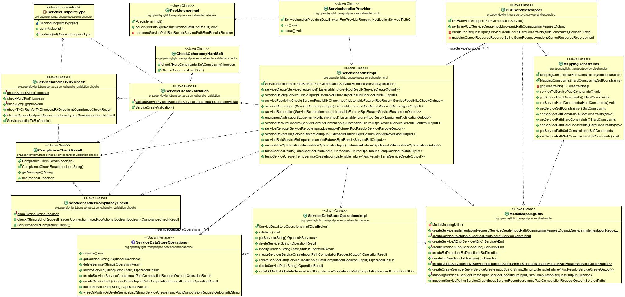
ServiceHandler Class Diagram
In this section we focus on the description of the main classes of the ServiceHandler bundle, it only provides information on the main classes.
ServicehandllerProvider registers ServicehandlerImpl class module to OpenDayLight RPC service registry and instantiates PceListenerImpl & RendererListenerImpl classes, which define the methods implementing the PCE and Renderer modules Listeners.
ServicehandlerImpl implements OrgOpenroadmServiceService interface, the YANG RPCs defined in module org-openroadm-service of OpenROADM.
PceListenerImpl implements TransportpcePceListener interface which is in charge of listening to PCE notifications.
RendererListenerImpl implements TransportpceRendererListener interface which is in charge of listening to Renderer notifications.
PCEServiceWrapper sends path-computation and cancel-resource-reserve to PCE module.
RendererServiceWrapper sends service-delete RPC to Renderer module.
ServiceDataStoreOperations is an OpenROADM Service operations API providing basic operations on services datastore.
ServiceDataStoreOperationsImpl implements ServiceDataStoreOperations interface.
ServiceCreateValidation checks if RPC service-create input is compliant.
ServicehandlerCompliancyCheck checks if sdnc-request-header in RPC input parameter is compliant.
ServicehandlerTxRxCheck checks if Tx/Rx info for A/Z end is not missing.
CheckCoherencyHardSoft checks if coherency between hard and soft constraints in rpc input parameters.
MappingConstraints maps Hard/soft constraint from OpenROADM to servicePath 1.5 models.
ModelMappingUtils is a set of tools to :
- create PCE RPCs inputs from Service handler inputs
- create Renderer RPCs inputs from Service handler inputs and PCE outputs
- map service handler RPCs response
- create OpenROADM service to be stored
- create ServicePath 1.5 service to be stored
StubPceServiceOperations implements PathComputationService interface to be able to stub the PCE module operations : path-computation and cancel-resource requests.
StubRendererServiceOperations implements RendererServiceOperations interface to be able to stub Renderer module operations : service-implementation and service-delete requests.
Service model (connections)
Openroadm members are welcome to check text here below and correct any issue if need be.
High level
Actually, two kind of services are proposed:
- service
- temporary service
A service can be permanent or non permanent with due-date and end-date. In order to reserve resources before service activation, a temporary service can be created (with exact same characteristics) and activated until the due-date is reached for the service.
| Type of service | Priority | Agreed | Comments |
|---|---|---|---|
| Service | [orange] P1 [Telia]P1 | ||
| Temp-service | [orange] P2 [Telia]P2, if as comment | Orange: For time-constrainted services, it is suggested to have it in P1 without resource reservation in a first step. |
Service header
By default, all non-optional parameters have to be managed unless further notice. Optional parameters are reviewed for implementation. Reviewers are free to add other optional parameters for P1 implementation
| leaf | Priority | comment |
|---|---|---|
| sdnc-request-header/request-id | [Orange] P1 [Telia]P1 | |
| sdnc-request-header/system-id | [Orange] P1 [Telia]P1 | useful to determine which application has asked for the service |
| administrative-state | [Orange] P1 [Telia]P1 | |
| operational-state | [Orange] P1 [Telia]P1 |
Service a&z ends
| Leaf | Priority | Comment |
|---|---|---|
| node-id | [Orange] P1 [Telia]P1 | for compliancy with PCE spec, node-id spec is required (service-handler will not determine by itself the node on which implementig the service) |
| Tx & Rx / port / port-type | [Orange] P2 [Telia]P2 | Useful since it specifies the type of expected port |
| Tx & Rx / port / port-name | [Orange] P1 [Telia]P2 | Important and needed for the same reason as node-id (port-name is the info available from topology model). Other info do not seem crucial from service description point of view. Still useful to have it all in one place. Otherwise, a visit to device model is needed. |
| Tx & Rx / lgx / xxx | [Orange] P2 [Telia] - | Defines the link from the transponder line-side up to the port pair of the add-drop through a cross-connect. Since we already know from topology (network model) on which port-pair the transponder is connected, what is the added value to give the LGX here ? |
| Tx & Rx / tail / xxx | [Orange] P2 [Telia]P2 | Defines the link from the transponder client-side up to the client equipment. We could imagine a tail model (not available from openroadm) that potentially limits connectivity (through connectivity matrix) between client equipment and client port of transponder. However, I suggests starting without constraint from the tail segment and start service from the transponder client-port in a first step. |
| user-label | [Orange] P1 [Telia]P1 | Label for service endpoint, defined by the user |
Hard & Soft constraints
keep them all
topology
fiber-span-srlg are listed in "other section". Therefore, this section focuses on nodes. Service model lists the set of devices being used by the service.
| Leaf | Priority | Comment |
|---|---|---|
| SRG-number | [Orange] P1 | mandatory info when node is edge ROADM |
| degree-number | [Orange] P1 | mandatory info when node is ROADM |
Other
| Leaf | Priority | Comment |
|---|---|---|
| due-date / end-date | [Orange] P1 [Telia]P2 | useful for BoD / calendaring use cases |
| customer/customer-contact/operator-contact | [Orange] P2 [Telia]P2 | |
| Latency | [Orange] P1 [Telia]P1 | |
| SRG numbers | [Orange] P1 [Telia]P1 |
Interface A - YANG API
Beyond the get-config / edit-config (or their equivalent in REST) on service model, following RPC are requested :
| RPC | Priority | Comment |
|---|---|---|
| service-create | [Orange] P1 | regarding inputs/outputs, cf service model |
| service-feasibility-check | [Orange] P1 | |
| equipment-notification | [Orange] ? | don't remember the purpose of this RPC... |
| service-delete | [Orange] P1 | |
| temp-service-create | [Orange] P3 | |
| temp-service-delete | [Orange] P3 | |
| service-roll | [Orange] P2 | |
| service-reconfigure | [Orange] P2 | |
| service-restoration | [Orange] P1 | |
| service-reversion | [Orange] P1 | |
| service-reroute | [Orange] P3 ? | don't see the big difference with service-roll |
| service-reroute-confirm | [Orange] P3 ? | don't see the big difference with service-roll |
| Notifications | Priority | Comment |
|---|---|---|
| service-rpc-result | what is the added valuue compared to the output of the rpc ? | |
| service-traffic-flow | [Orange] P1 | How can we change administrative state of services ? through "edit-config" (or some equivalent in REST) of the service ? |
| service-notification | [Orange] P1 | This Notification that a service has been added, modified or removed. |
Issues to be discussed :
- response-code type is string. This is not accurate enough for an API. Should be enum (invalid, created, pending,...) ?
- ack-final-indicator: shold be enum also
Interface B
Interface B relies on service path Yang model and rpc "path-calculation-request".
A tree view (Yang Model sent separately by email) is proposed here to modelize the input/output parameters to be passed over B interface. These parameters come from the service model with still some variations. These variations come mainly from PCE requirements section (but not only).
For discussion
module: org-openroadm-servicepath
  +--rw service-path-list
     +--rw service-paths* [service-path]
        +--rw service-path-name          string
        +--rw service-handler-header
        |  +--rw request-id    string
        +--rw service-a-end
        |  +--rw service-format    org-openroadm-common-service-types:service-format
        |  +--rw service-rate      uint32
        |  +--rw clli              string
        |  +--rw node-id?          string
        |  +--rw tx-direction
        |  |  +--rw port
        |  |     +--rw port-device-name?   string
        |  |     +--rw port-type?          string
        |  |     +--rw port-name?          string
        |  |     +--rw port-rack?          string
        |  |     +--rw port-shelf?         string
        |  |     +--rw port-slot?          string
        |  |     +--rw port-sub-slot?      string
        |  +--rw rx-direction
        |     +--rw port
        |        +--rw port-device-name?   string
        |        +--rw port-type?          string
        |        +--rw port-name?          string
        |        +--rw port-rack?          string
        |        +--rw port-shelf?         string
        |        +--rw port-slot?          string
        |        +--rw port-sub-slot?      string
        +--rw service-z-end
        |  +--rw service-format    org-openroadm-common-service-types:service-format
        |  +--rw service-rate      uint32
        |  +--rw clli              string
        |  +--rw node-id?          string
        |  +--rw tx-direction
        |  |  +--rw port
        |  |     +--rw port-device-name?   string
        |  |     +--rw port-type?          string
        |  |     +--rw port-name?          string
        |  |     +--rw port-rack?          string
        |  |     +--rw port-shelf?         string
        |  |     +--rw port-slot?          string
        |  |     +--rw port-sub-slot?      string
        |  +--rw rx-direction
        |     +--rw port
        |        +--rw port-device-name?   string
        |        +--rw port-type?          string
        |        +--rw port-name?          string
        |        +--rw port-rack?          string
        |        +--rw port-shelf?         string
        |        +--rw port-slot?          string
        |        +--rw port-sub-slot?      string
        +--rw hard-constraints
        |  +--rw customer-code*   string
        |  +--rw (co-routing-or-general)?
        |     +--:(general)
        |     |  +--rw diversity
        |     |  |  +--rw existing-service*                 string
        |     |  |  +--rw existing-service-applicability
        |     |  |     +--rw clli?   boolean
        |     |  |     +--rw node?   boolean
        |     |  |     +--rw srlg?   boolean
        |     |  +--rw exclude_
        |     |  |  +--rw SRLG*                      string
        |     |  |  +--rw clli*                      string
        |     |  |  +--rw node-id*                   string
        |     |  |  +--rw supporting-service-name*   string
        |     |  |  +--rw affinity?                  uint32
        |     |  +--rw include_
        |     |  |  +--rw ordered-hops* [hop-number]
        |     |  |     +--rw hop-number    uint16
        |     |  |     +--rw hop-type
        |     |  |        +--rw (hop-type)?
        |     |  |           +--:(SRLG)
        |     |  |           |  +--rw SRLG?      string
        |     |  |           +--:(clli)
        |     |  |           |  +--rw clli?      string
        |     |  |           +--:(node)
        |     |  |              +--rw node-id?   string
        |     |  +--rw latency
        |     |     +--rw max-latency?   uint32
        |     +--:(co-routing)
        |        +--rw co-routing
        |           +--rw existing-service*   string
        +--rw soft-constraints
        |  +--rw customer-code*   string
        |  +--rw (co-routing-or-general)?
        |     +--:(general)
        |     |  +--rw diversity
        |     |  |  +--rw existing-service*                 string
        |     |  |  +--rw existing-service-applicability
        |     |  |     +--rw clli?   boolean
        |     |  |     +--rw node?   boolean
        |     |  |     +--rw srlg?   boolean
        |     |  +--rw exclude_
        |     |  |  +--rw SRLG*                      string
        |     |  |  +--rw clli*                      string
        |     |  |  +--rw node-id*                   string
        |     |  |  +--rw supporting-service-name*   string
        |     |  |  +--rw affinity?                  uint32
        |     |  +--rw include_
        |     |  |  +--rw ordered-hops* [hop-number]
        |     |  |     +--rw hop-number    uint16
        |     |  |     +--rw hop-type
        |     |  |        +--rw (hop-type)?
        |     |  |           +--:(SRLG)
        |     |  |           |  +--rw SRLG?      string
        |     |  |           +--:(clli)
        |     |  |           |  +--rw clli?      string
        |     |  |           +--:(node)
        |     |  |              +--rw node-id?   string
        |     |  +--rw latency
        |     |     +--rw max-latency?   uint32
        |     +--:(co-routing)
        |        +--rw co-routing
        |           +--rw existing-service*   string
        +--rw pce-metric?                enumeration
        +--rw locally-protected-links?   boolean
        +--rw latency?                   uint32
        +--rw fiber-span-srlgs*          string
        +--rw equipment-srgs* [srg-number]
        |  +--rw srg-number    uint16
        +--rw supporting-service-name*   string
        +--rw path-description
           +--rw aToZ-direction
           |  +--rw aToZ-wavelength-number    uint32
           |  +--rw rate                      uint32
           |  +--rw modulation-format?        string
           |  +--rw aToZ* [id]
           |     +--rw id          string
           |     +--rw resource
           |        +--rw (resource)?
           |           +--:(termination-point)
           |           |  +--rw tp-id?     string
           |           |  +--rw node-id?   string
           |           +--:(link)
           |           |  +--rw link-id?   string
           |           +--:(node)
           |              +--rw node-id?   string
           +--rw zToA-direction
              +--rw zToA-wavelength-number    uint32
              +--rw rate                      uint32
              +--rw modulation-format?        string
              +--rw zToA* [id]
                 +--rw id          string
                 +--rw resource
                    +--rw (resource)?
                       +--:(termination-point)
                       |  +--rw tp-id?     string
                       |  +--rw node-id?   string
                       +--:(link)
                       |  +--rw link-id?   string
                       +--:(node)
                          +--rw node-id?   string
rpcs:
  +---x path-computation-request
  |  +---w input
  |  |  +---w service-name               string
  |  |  +---w resource-reserve           boolean
  |  |  +---w service-handler-header
  |  |  |  +---w request-id    string
  |  |  +---w service-a-end
  |  |  |  +---w service-format    org-openroadm-common-service-types:service-format
  |  |  |  +---w service-rate      uint32
  |  |  |  +---w clli              string
  |  |  |  +---w node-id?          string
  |  |  |  +---w tx-direction
  |  |  |  |  +---w port
  |  |  |  |     +---w port-device-name?   string
  |  |  |  |     +---w port-type?          string
  |  |  |  |     +---w port-name?          string
  |  |  |  |     +---w port-rack?          string
  |  |  |  |     +---w port-shelf?         string
  |  |  |  |     +---w port-slot?          string
  |  |  |  |     +---w port-sub-slot?      string
  |  |  |  +---w rx-direction
  |  |  |     +---w port
  |  |  |        +---w port-device-name?   string
  |  |  |        +---w port-type?          string
  |  |  |        +---w port-name?          string
  |  |  |        +---w port-rack?          string
  |  |  |        +---w port-shelf?         string
  |  |  |        +---w port-slot?          string
  |  |  |        +---w port-sub-slot?      string
  |  |  +---w service-z-end
  |  |  |  +---w service-format    org-openroadm-common-service-types:service-format
  |  |  |  +---w service-rate      uint32
  |  |  |  +---w clli              string
  |  |  |  +---w node-id?          string
  |  |  |  +---w tx-direction
  |  |  |  |  +---w port
  |  |  |  |     +---w port-device-name?   string
  |  |  |  |     +---w port-type?          string
  |  |  |  |     +---w port-name?          string
  |  |  |  |     +---w port-rack?          string
  |  |  |  |     +---w port-shelf?         string
  |  |  |  |     +---w port-slot?          string
  |  |  |  |     +---w port-sub-slot?      string
  |  |  |  +---w rx-direction
  |  |  |     +---w port
  |  |  |        +---w port-device-name?   string
  |  |  |        +---w port-type?          string
  |  |  |        +---w port-name?          string
  |  |  |        +---w port-rack?          string
  |  |  |        +---w port-shelf?         string
  |  |  |        +---w port-slot?          string
  |  |  |        +---w port-sub-slot?      string
  |  |  +---w hard-constraints
  |  |  |  +---w customer-code*   string
  |  |  |  +---w (co-routing-or-general)?
  |  |  |     +--:(general)
  |  |  |     |  +---w diversity
  |  |  |     |  |  +---w existing-service*                 string
  |  |  |     |  |  +---w existing-service-applicability
  |  |  |     |  |     +---w clli?   boolean
  |  |  |     |  |     +---w node?   boolean
  |  |  |     |  |     +---w srlg?   boolean
  |  |  |     |  +---w exclude_
  |  |  |     |  |  +---w SRLG*                      string
  |  |  |     |  |  +---w clli*                      string
  |  |  |     |  |  +---w node-id*                   string
  |  |  |     |  |  +---w supporting-service-name*   string
  |  |  |     |  |  +---w affinity?                  uint32
  |  |  |     |  +---w include_
  |  |  |     |  |  +---w ordered-hops* [hop-number]
  |  |  |     |  |     +---w hop-number    uint16
  |  |  |     |  |     +---w hop-type
  |  |  |     |  |        +---w (hop-type)?
  |  |  |     |  |           +--:(SRLG)
  |  |  |     |  |           |  +---w SRLG?      string
  |  |  |     |  |           +--:(clli)
  |  |  |     |  |           |  +---w clli?      string
  |  |  |     |  |           +--:(node)
  |  |  |     |  |              +---w node-id?   string
  |  |  |     |  +---w latency
  |  |  |     |     +---w max-latency?   uint32
  |  |  |     +--:(co-routing)
  |  |  |        +---w co-routing
  |  |  |           +---w existing-service*   string
  |  |  +---w soft-constraints
  |  |  |  +---w customer-code*   string
  |  |  |  +---w (co-routing-or-general)?
  |  |  |     +--:(general)
  |  |  |     |  +---w diversity
  |  |  |     |  |  +---w existing-service*                 string
  |  |  |     |  |  +---w existing-service-applicability
  |  |  |     |  |     +---w clli?   boolean
  |  |  |     |  |     +---w node?   boolean
  |  |  |     |  |     +---w srlg?   boolean
  |  |  |     |  +---w exclude_
  |  |  |     |  |  +---w SRLG*                      string
  |  |  |     |  |  +---w clli*                      string
  |  |  |     |  |  +---w node-id*                   string
  |  |  |     |  |  +---w supporting-service-name*   string
  |  |  |     |  |  +---w affinity?                  uint32
  |  |  |     |  +---w include_
  |  |  |     |  |  +---w ordered-hops* [hop-number]
  |  |  |     |  |     +---w hop-number    uint16
  |  |  |     |  |     +---w hop-type
  |  |  |     |  |        +---w (hop-type)?
  |  |  |     |  |           +--:(SRLG)
  |  |  |     |  |           |  +---w SRLG?      string
  |  |  |     |  |           +--:(clli)
  |  |  |     |  |           |  +---w clli?      string
  |  |  |     |  |           +--:(node)
  |  |  |     |  |              +---w node-id?   string
  |  |  |     |  +---w latency
  |  |  |     |     +---w max-latency?   uint32
  |  |  |     +--:(co-routing)
  |  |  |        +---w co-routing
  |  |  |           +---w existing-service*   string
  |  |  +---w pce-metric?                enumeration
  |  |  +---w locally-protected-links?   boolean
  |  +--ro output
  |     +--ro configuration-response-common
  |     |  +--ro request-id             string
  |     |  +--ro response-code          string
  |     |  +--ro response-message?      string
  |     |  +--ro ack-final-indicator    string
  |     +--ro response-parameters
  |        +--ro hard-constraints
  |        |  +--ro customer-code*   string
  |        |  +--ro (co-routing-or-general)?
  |        |     +--:(general)
  |        |     |  +--ro diversity
  |        |     |  |  +--ro existing-service*                 string
  |        |     |  |  +--ro existing-service-applicability
  |        |     |  |     +--ro clli?   boolean
  |        |     |  |     +--ro node?   boolean
  |        |     |  |     +--ro srlg?   boolean
  |        |     |  +--ro exclude_
  |        |     |  |  +--ro SRLG*                      string
  |        |     |  |  +--ro clli*                      string
  |        |     |  |  +--ro node-id*                   string
  |        |     |  |  +--ro supporting-service-name*   string
  |        |     |  |  +--ro affinity?                  uint32
  |        |     |  +--ro include_
  |        |     |  |  +--ro ordered-hops* [hop-number]
  |        |     |  |     +--ro hop-number    uint16
  |        |     |  |     +--ro hop-type
  |        |     |  |        +--ro (hop-type)?
  |        |     |  |           +--:(SRLG)
  |        |     |  |           |  +--ro SRLG?      string
  |        |     |  |           +--:(clli)
  |        |     |  |           |  +--ro clli?      string
  |        |     |  |           +--:(node)
  |        |     |  |              +--ro node-id?   string
  |        |     |  +--ro latency
  |        |     |     +--ro max-latency?   uint32
  |        |     +--:(co-routing)
  |        |        +--ro co-routing
  |        |           +--ro existing-service*   string
  |        +--ro soft-constraints
  |        |  +--ro customer-code*   string
  |        |  +--ro (co-routing-or-general)?
  |        |     +--:(general)
  |        |     |  +--ro diversity
  |        |     |  |  +--ro existing-service*                 string
  |        |     |  |  +--ro existing-service-applicability
  |        |     |  |     +--ro clli?   boolean
  |        |     |  |     +--ro node?   boolean
  |        |     |  |     +--ro srlg?   boolean
  |        |     |  +--ro exclude_
  |        |     |  |  +--ro SRLG*                      string
  |        |     |  |  +--ro clli*                      string
  |        |     |  |  +--ro node-id*                   string
  |        |     |  |  +--ro supporting-service-name*   string
  |        |     |  |  +--ro affinity?                  uint32
  |        |     |  +--ro include_
  |        |     |  |  +--ro ordered-hops* [hop-number]
  |        |     |  |     +--ro hop-number    uint16
  |        |     |  |     +--ro hop-type
  |        |     |  |        +--ro (hop-type)?
  |        |     |  |           +--:(SRLG)
  |        |     |  |           |  +--ro SRLG?      string
  |        |     |  |           +--:(clli)
  |        |     |  |           |  +--ro clli?      string
  |        |     |  |           +--:(node)
  |        |     |  |              +--ro node-id?   string
  |        |     |  +--ro latency
  |        |     |     +--ro max-latency?   uint32
  |        |     +--:(co-routing)
  |        |        +--ro co-routing
  |        |           +--ro existing-service*   string
  |        +--ro pce-metric?                enumeration
  |        +--ro locally-protected-links?   boolean
  |        +--ro path-description
  |           +--ro aToZ-direction
  |           |  +--ro aToZ-wavelength-number    uint32
  |           |  +--ro rate                      uint32
  |           |  +--ro modulation-format?        string
  |           |  +--ro aToZ* [id]
  |           |     +--ro id          string
  |           |     +--ro resource
  |           |        +--ro (resource)?
  |           |           +--:(termination-point)
  |           |           |  +--ro tp-id?     string
  |           |           |  +--ro node-id?   string
  |           |           +--:(link)
  |           |           |  +--ro link-id?   string
  |           |           +--:(node)
  |           |              +--ro node-id?   string
  |           +--ro zToA-direction
  |              +--ro zToA-wavelength-number    uint32
  |              +--ro rate                      uint32
  |              +--ro modulation-format?        string
  |              +--ro zToA* [id]
  |                 +--ro id          string
  |                 +--ro resource
  |                    +--ro (resource)?
  |                       +--:(termination-point)
  |                       |  +--ro tp-id?     string
  |                       |  +--ro node-id?   string
  |                       +--:(link)
  |                       |  +--ro link-id?   string
  |                       +--:(node)
  |                          +--ro node-id?   string
notifications:
  +---n service-path-rpc-result
  |  +--ro notification-type?   org-openroadm-common-service-path-types:service-path-notification-types
  |  +--ro path-description
  |  |  +--ro aToZ-direction
  |  |  |  +--ro aToZ-wavelength-number    uint32
  |  |  |  +--ro rate                      uint32
  |  |  |  +--ro modulation-format?        string
  |  |  |  +--ro aToZ* [id]
  |  |  |     +--ro id          string
  |  |  |     +--ro resource
  |  |  |        +--ro (resource)?
  |  |  |           +--:(termination-point)
  |  |  |           |  +--ro tp-id?     string
  |  |  |           |  +--ro node-id?   string
  |  |  |           +--:(link)
  |  |  |           |  +--ro link-id?   string
  |  |  |           +--:(node)
  |  |  |              +--ro node-id?   string
  |  |  +--ro zToA-direction
  |  |     +--ro zToA-wavelength-number    uint32
  |  |     +--ro rate                      uint32
  |  |     +--ro modulation-format?        string
  |  |     +--ro zToA* [id]
  |  |        +--ro id          string
  |  |        +--ro resource
  |  |           +--ro (resource)?
  |  |              +--:(termination-point)
  |  |              |  +--ro tp-id?     string
  |  |              |  +--ro node-id?   string
  |  |              +--:(link)
  |  |              |  +--ro link-id?   string
  |  |              +--:(node)
  |  |                 +--ro node-id?   string
  |  +--ro status               rpc-status-ex
  |  +--ro service-name         string
  |  +--ro actual-date?         yang:date-and-time
Interface C
based on service path Yang model and rpc "service implementation-request" & "service-delete".
Here below the tree view of the two RPCs, and of the notification service-rpc-result-sp
module: org-openroadm-servicepath
rpcs :
  +---x service-implementation-request
  |  +---w input
  |  |  +---w service-name              string
  |  |  +---w service-handler-header
  |  |  |  +---w request-id    string
  |  |  +---w service-a-end
  |  |  |  +---w service-format    org-openroadm-common-service-types:service-format
  |  |  |  +---w service-rate      uint32
  |  |  |  +---w clli              string
  |  |  |  +---w node-id?          string
  |  |  |  +---w tx-direction
  |  |  |  |  +---w port
  |  |  |  |     +---w port-device-name?   string
  |  |  |  |     +---w port-type?          string
  |  |  |  |     +---w port-name?          string
  |  |  |  |     +---w port-rack?          string
  |  |  |  |     +---w port-shelf?         string
  |  |  |  |     +---w port-slot?          string
  |  |  |  |     +---w port-sub-slot?      string
  |  |  |  +---w rx-direction
  |  |  |     +---w port
  |  |  |        +---w port-device-name?   string
  |  |  |        +---w port-type?          string
  |  |  |        +---w port-name?          string
  |  |  |        +---w port-rack?          string
  |  |  |        +---w port-shelf?         string
  |  |  |        +---w port-slot?          string
  |  |  |        +---w port-sub-slot?      string
  |  |  +---w service-z-end
  |  |  |  +---w service-format    org-openroadm-common-service-types:service-format
  |  |  |  +---w service-rate      uint32
  |  |  |  +---w clli              string
  |  |  |  +---w node-id?          string
  |  |  |  +---w tx-direction
  |  |  |  |  +---w port
  |  |  |  |     +---w port-device-name?   string
  |  |  |  |     +---w port-type?          string
  |  |  |  |     +---w port-name?          string
  |  |  |  |     +---w port-rack?          string
  |  |  |  |     +---w port-shelf?         string
  |  |  |  |     +---w port-slot?          string
  |  |  |  |     +---w port-sub-slot?      string
  |  |  |  +---w rx-direction
  |  |  |     +---w port
  |  |  |        +---w port-device-name?   string
  |  |  |        +---w port-type?          string
  |  |  |        +---w port-name?          string
  |  |  |        +---w port-rack?          string
  |  |  |        +---w port-shelf?         string
  |  |  |        +---w port-slot?          string
  |  |  |        +---w port-sub-slot?      string
  |  |  +---w path-description
  |  |     +---w aToZ-direction
  |  |     |  +---w aToZ-wavelength-number    uint32
  |  |     |  +---w rate                      uint32
  |  |     |  +---w modulation-format?        string
  |  |     |  +---w aToZ* [id]
  |  |     |     +---w id          string
  |  |     |     +---w resource
  |  |     |        +---w (resource)?
  |  |     |           +--:(termination-point)
  |  |     |           |  +---w tp-id?     string
  |  |     |           |  +---w node-id?   string
  |  |     |           +--:(link)
  |  |     |           |  +---w link-id?   string
  |  |     |           +--:(node)
  |  |     |              +---w node-id?   string
  |  |     +---w zToA-direction
  |  |        +---w zToA-wavelength-number    uint32
  |  |        +---w rate                      uint32
  |  |        +---w modulation-format?        string
  |  |        +---w zToA* [id]
  |  |           +---w id          string
  |  |           +---w resource
  |  |              +---w (resource)?
  |  |                 +--:(termination-point)
  |  |                 |  +---w tp-id?     string
  |  |                 |  +---w node-id?   string
  |  |                 +--:(link)
  |  |                 |  +---w link-id?   string
  |  |                 +--:(node)
  |  |                    +---w node-id?   string
  |  +--ro output
  |     +--ro configuration-response-common
  |        +--ro request-id             string
  |        +--ro response-code          string
  |        +--ro response-message?      string
  |        +--ro ack-final-indicator    string
  +---x service-delete
     +---w input
     |  +---w service-name              string
     |  +---w service-handler-header
     |     +---w request-id    string
     +--ro output
        +--ro configuration-response-common
           +--ro request-id             string
           +--ro response-code          string
           +--ro response-message?      string
           +--ro ack-final-indicator    string
+---x cancel-resource-reserve
  |  +---w input
  |  |  +---w service-name              string
  |  |  +---w service-handler-header
  |  |     +---w request-id    string
  |  +--ro output
  |     +--ro configuration-response-common
  |        +--ro request-id             string
  |        +--ro response-code          string
  |        +--ro response-message?      string
  |        +--ro ack-final-indicator    string
notifications:
  +---n service-rpc-result-sp
     +--ro notification-type?   org-openroadm-common-service-path-types:service-path-notification-types
     +--ro path-topology
     |  +--ro aToZ* [id]
     |  |  +--ro id              string
     |  |  +--ro hop-type?       enumeration
     |  |  +--ro device
     |  |  |  +--ro node-id?   string
     |  |  +--ro resource
     |  |  |  +--ro (resource)?
     |  |  |     +--:(circuit-pack)
     |  |  |     |  +--ro circuit-pack-name     string
     |  |  |     +--:(port)
     |  |  |     |  +--ro port
     |  |  |     |     +--ro circuit-pack-name    string
     |  |  |     |     +--ro port-name?           string
     |  |  |     +--:(connection)
     |  |  |     |  +--ro connection-number     string
     |  |  |     +--:(physical-link)
     |  |  |     |  +--ro physical-link-name    string
     |  |  |     +--:(internal-link)
     |  |  |     |  +--ro internal-link-name    string
     |  |  |     +--:(shelf)
     |  |  |     |  +--ro shelf-name            string
     |  |  |     +--:(srg)
     |  |  |     |  +--ro srg-number            uint16
     |  |  |     +--:(degree)
     |  |  |     |  +--ro degree-number         uint16
     |  |  |     +--:(service)
     |  |  |     |  +--ro service-name          string
     |  |  |     +--:(interface)
     |  |  |        +--ro interface-name        string
     |  |  +--ro resourceType
     |  |     +--ro type         resource-type-enum
     |  |     +--ro extension?   string
     |  +--ro zToA* [id]
     |     +--ro id              string
     |     +--ro hop-type?       enumeration
     |     +--ro device
     |     |  +--ro node-id?   string
     |     +--ro resource
     |     |  +--ro (resource)?
     |     |     +--:(circuit-pack)
     |     |     |  +--ro circuit-pack-name     string
     |     |     +--:(port)
     |     |     |  +--ro port
     |     |     |     +--ro circuit-pack-name    string
     |     |     |     +--ro port-name?           string
     |     |     +--:(connection)
     |     |     |  +--ro connection-number     string
     |     |     +--:(physical-link)
     |     |     |  +--ro physical-link-name    string
     |     |     +--:(internal-link)
     |     |     |  +--ro internal-link-name    string
     |     |     +--:(shelf)
     |     |     |  +--ro shelf-name            string
     |     |     +--:(srg)
     |     |     |  +--ro srg-number            uint16
     |     |     +--:(degree)
     |     |     |  +--ro degree-number         uint16
     |     |     +--:(service)
     |     |     |  +--ro service-name          string
     |     |     +--:(interface)
     |     |        +--ro interface-name        string
     |     +--ro resourceType
     |        +--ro type         resource-type-enum
     |        +--ro extension?   string
     +--ro status               rpc-status-ex
     +--ro service-name         string
     +--ro actual-date?         yang:date-and-time
Service handler logic
proposal ongoing...
service creation
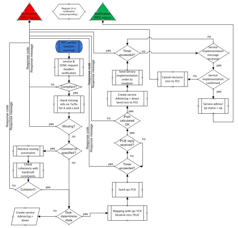
Brief explanation:
- Upon receipt of service-create RPC, service header and sdnc-request header compliancy are verified.
- If compliant, service-request parameters are verified in order to check if there is no missing parameter that prevents calculating a path and implement a service.
- If OK, common-id is verified in order to see if there is no routing policy provided. If yes, the routing constraints of the policy are recovered and coherency with hard/soft constraints provided in the input of the RPC.
- If OK, service due-time is verified. For any service to be activated later on, it is proposed to store them and wait for due-time to become equal to immediate (see xx). This behavior shall be improved in further release.
- Before sending the PCE request, input data need to be formatted according to the Service Handler - PCE interface data model.
- Once PCE request is being sent to the PCE on interface B, PCE reply is expected until a timer expires.
- If PCE reply is received before timer expiration with a positive result, a service is created with admin and operational status 'down'.
- A service implementation request is sent to the render on interface C.
- If a positive message is received from the renderer, service admin / operational status is changed to 'up'.
- For any case of failure, response-code, response message and ack-final-indicator shall be provided.

service feasibility check
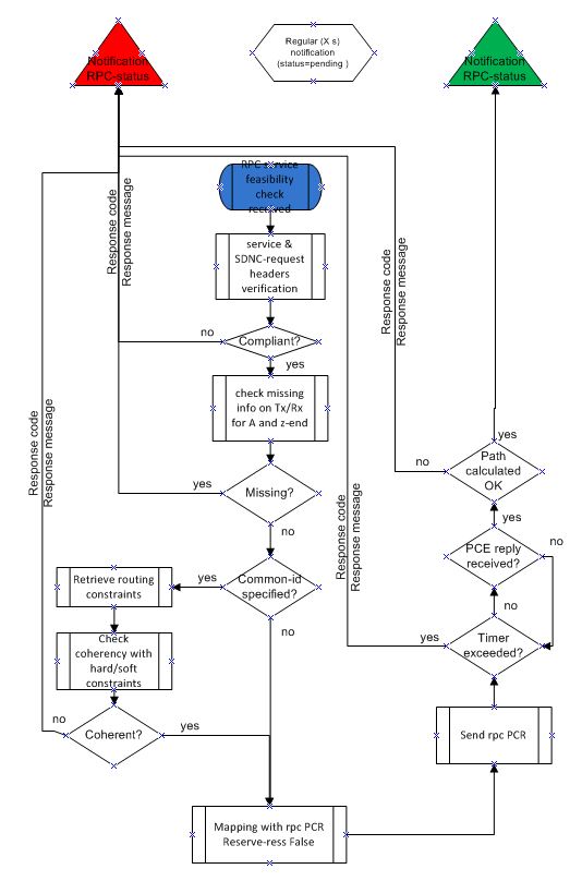
service delete
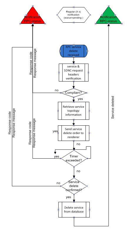
service modify:
one or several technical parameters are modified in service description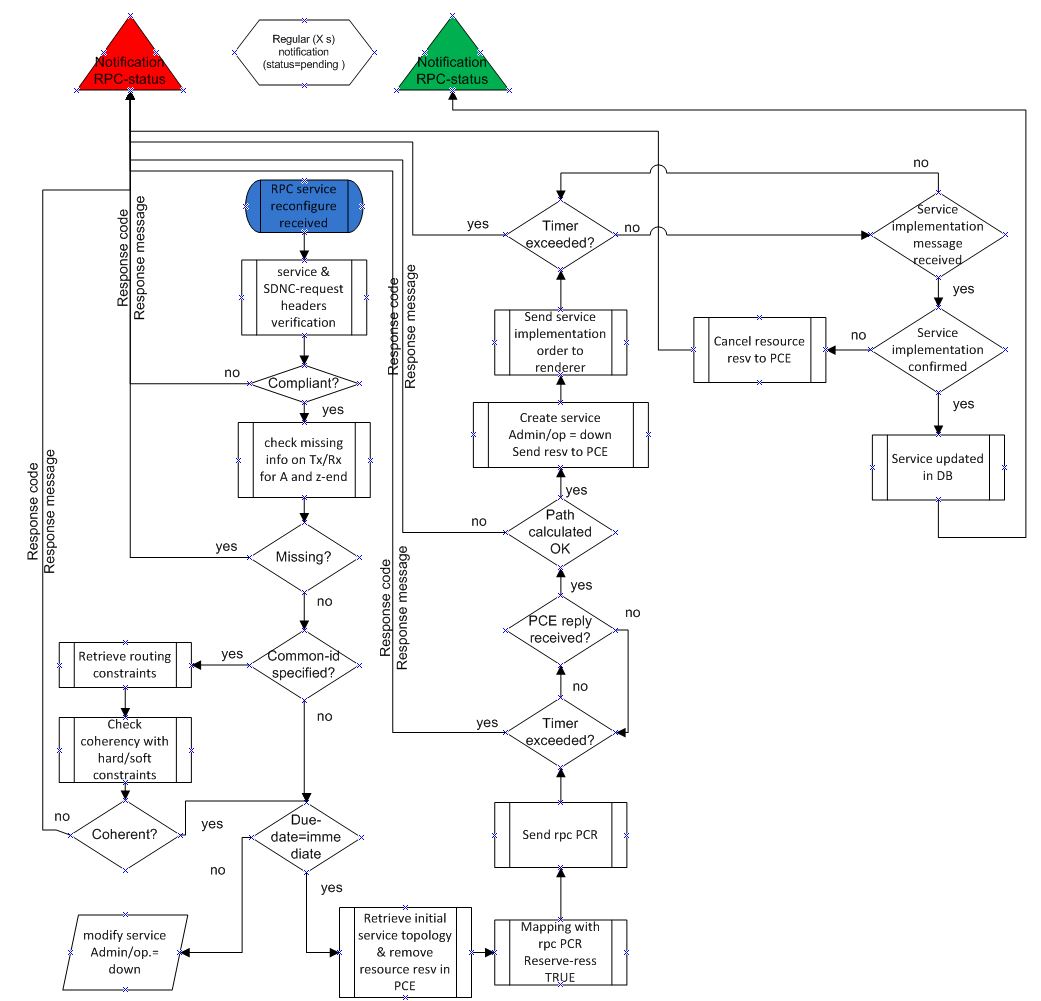
service restore:
service has been reported to be down (for network issue) and a restoration is being requested

NB: service delete is sent to the renderer for deletion in the network. However, the service is not deleted in service database. Only its path is cleared since removed from the network.
service reversion:
return to nominal path is requested for a service previously rerouted/restored. This still requires to store nominal path. For a service being restored, only the new path path is stored (in the service model).
non-permanent services management
in-life service management
services can be disturbed because of some network events. An OAM function in ODL controller is in charge of collecting network events, SLA measurements and updates services accordingly. Service notfications are then sent to any external function having subscribed to these notifications. However, OAM function is out of the scope of transportpce project.
- ...
Optical validation
This section gives an overview of how optical validation function is invoked in different implementations of the PCE.
Ericsson implementation
In the following flowchart the optical validation function is highlighted inside the process of path computation (please note that the detail is very rough in gives only a superficial idea of the actual algorithm). The base is the Dijkstra algorithm, which is augmented with the logic needed to cope with additional constraints, including optical validation, as needed.
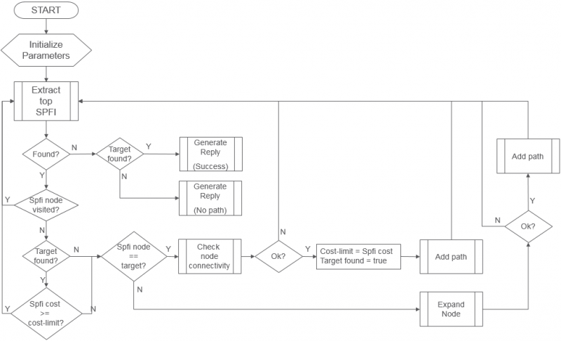
- Initialize parameters : Initialize the path computation parameters, checking for the correctness of the path computation request, verifying conditions preventing successful path computation. A first SPFI (see below) is generated and inserted in the heap used by the Dijkstra algorithm.
- Extract top SPFI : The relaxation step of the Dijkstra algorithm (that is the propagation of the algorithm along the links of the topology) is named SPFI (Shortest Path First Information). It's used to transport information related to the path computation, like all the cumulative attributes (including metrics) and links with other SPFI, allowing to build the tree of the equal cost optimal paths between source and destination. SPFIs are maintained inside a heap (a priority queue) ordered by the objective metric used during the path computation. The best candidate SPFI is therefore always available on top of the heap.
- Check node connectivity : in optical (and also in other technologies where NEs don't provide full connectivity among their interfaces) it's needed to check that two interfaces can be connected each other. Doing so, it's also possible to collect information about which optical equipment (amplifiers, dcms and more) is traversed.
- Add path : performs operation on the current SPFI in order to link it to previous and sibling SPFIs, with the objective to build the equal cost path tree.
- Expand node : does the visit of the network according to Dijkstra algorithm. Details of this step in the following schema:
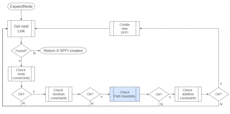
- Get Next Link : all the links of the current node (the one referred in the current SPFI) are visited.
- Check node connectivity : as before, it's assessed the possibility to interconnect the incoming link (the one referred in the current SPFI) to the outgoing link (the one just selected by the "Get Next Link" operation).
- Check Boolean constraints : check if there is some attribute of the outgoing link which makes it not suitable to be used by the candidate path (e.g. link disabled, or locked, or with affinities not in compliance with the requirements, and more)
- Check path feasibility : invoke the path feasibility function against the current candidate path (from ingress up to the outgoing link/node). If the path is not feasible no propagation happens through the outgoing link. This is the place where this operation happens (only for optical networks of course). Doing it during the path computation, allows to guarantee the end-to-end feasibility, if it's possible.
- Check additive constraints : check constraints against metrics or other cumulative attributes. E.g. bounds on # of hops, or TE-metric, or latency. Here it's also done the check against lambda availability (to run the RWA exercise).
- Create new SPFI : if the outgoing link passes all the check, a new SPFI is created and populated with the new link and the relevant target node, the new computed metrics, and other attributes. It is then stored in the heap in the order of cost (the metric selected for optimization).
Optical Line Management
OLM description
Optical Line Management module implements two main features : it is responsible for setting up the optical power levels on the different interfaces, and is in charge of adjusting these settings across the life of the optical infrastructure.
After the different connections have been established in the ROADMS, between 2 Degrees for an express path, or between a SRG and a Degree for an Add or Drop path; meaning the devices have set WSS and all other required elements to provide path continuity, power setting are provided as attributes of these connections. This allows the device to set all complementary elements such as VOAs, to guaranty that the signal is launched at a correct power level (in accordance to the specifications) in the fiber span. This also applies to X-Ponders, as their output power must comply with the specifications defined for the Add/Drop ports (SRG) of the ROADM. OLM has the responsibility of calculating the right power settings, sending it to the device, and check the PM retrieved from the device to verify that the setting was correctly applied and the configuration was successfully completed.
OLM requirements
As OpenROADM MSA was selected for the initial implementation of TransportPCE, OLM shall respect the procedures defined in the Device White paper (Provisioning action use cases / Connection management) to set connections and power levels, as well as the OpenROADM specifications, both available at OpenROADM public site (Download)
Basic Renderer
Renderer description
The Renderer module is responsible for configuring the equipment after a service path has been defined by the Service Handler. The full process that we call “Renderer Service Operation” includes the management of connections implemented through the “Device Rendering” function, and power levels setting which relies on the OLM module, called by the Renderer.
The global process “Renderer Service Operation” relies on service-implementation-request and service-delete rpcs, defined in service-path 1.5 yang module to allow for RESTCONF service between the Service Handler and Renderer. These RPC could be used in case of future extension or development of additional modules that could remain external or be directly integrated in transportPCE.
The Device rendering function dedicated to connection setting inside the Renderer, relies on another rpc : service-path, defined in the server module of the rpc (transportpce-renderer). This last is used as an API for RESTCONF service between transportPCE internal modules : Topology Management, Service Handler, Renderer as well the Mapping Module bridging the abstracted topology used for path computation, (“path-description” of the service-path) with the detailed topology including device elements such as circuit-packs and ports (“topology” of the service as defined in the service Open ROADM model).
On service creation, the Service Handler uses service-implementation-request rpc to provide the path to the Renderer and trigger connections creation in the equipment. On service deletion, the Service Handler uses service-delete rpc. The path associated to the service is available in the service-list or the temp-service-list (depending on the type of service: regular versus temporary) of the MD-SAL DataStore. The Renderer then sets / deletes connections in the Netconf equipment according to the service path that has been defined for this specific service.
In the global path creation process, after connections have been correctly sets on the equipment across the path in the forward and the reverse direction, the Renderer relies on the OLM module to set the power levels on the equipment. If all connections cannot be set on the end to end path, the Rollback module is invoked to reset the different connections that were established during the path creation, so that equipment configuration goes back to its initial configuration.
Functional behavior of the renderer is based on D interface and device interface.
- D interface is addressed in service-handler section (ServiceHandler/servicerequest).
- the device interface is the netconf Yang interface based on Openroadm 1.2 device model.
Renderer Implementation
In this section we focus on the description of the main classes of the Renderer bundle. Thus this description shall not be considered as exhaustive. It only provides information on the main building blocks of the Renderer, to clarify its purpose and give some high level details on its implementation.
Renderer Provider and RPC implementation
RendererProvider class, at initialization registers to the rpc service, and instantiates TransportPCEServicePathRPCImpl & DeviceRendererRPCImpl classes, which define the methods implementing the RESTCONF services associated with the external APIs into the Renderer application.
DeviceRendererRPCImpl implements RendererService interface (automatically generated from Yang models) . It includes three main methods :
- servicePath used to provision (create operation), or de-provision (delete operation) the device for a given wavelength and a list of nodes with each node listing its termination points .
- createOtsOms used to provision OTS and OMS interfaces on the ROADM to ROADM link if this was not performed during the initial commissioning of the WDM lines.
- rendererRollback which rollbacks created interfaces and cross-connects if for some reason the service path could not be correctly created end to end.
TransportPCEServicePathRPCImpl implements transportpceServicepathService interface (automatically generated from Yang models) . It includes two main methods currently implemented : ServiceImplementationRequest and serviceDelete which corresponds to the rpcs defined in the Service-path 1.5 yang model. cancelresourceReserve method is currently not implemented. It is associated with the notion of temporary service that can be created between to ROADMs termination points, waiting until transponders are provisioned at both ends of the service path.
The Device Renderering service
DeviceRendererServiceImpl implements DeviceRendererService Interface, with the following public methods :
- setupServicePath : set's wavelength path, creating interfaces and cross connections in ROADMs. and creating a cross connect between source and destination tps. The path to configure is a list of Nodes with source and destination tps. This method first populates the service-node-lists in the Configuration Datastore for alarm-suppression with the all the nodes included in the service-path to configure through alarmSuppressionNodeRegistration method. It then sets in parallel on the different nodes all interfaces required to support the services on source and destination points (Och, OTU4 and ODU4 interfaces on the wavelength path, 100GE interfaces on the client side of transponders). To do this, it relies on OpenRoadmInterfaceFactory methods. After all interfaces have been created, it then sets unidirectional connections between tps (PP-TTP, TTP-TTP, TTP-PP) in the ROADMs; relying on CrossConnect postCrossConnect method. The successful creation of the connection is checked using CrossConnect.getConnectionPortTrail method which returns the ports used for the connection. When a cross-connection has been successfully created, the topology of the service (detailed list of the port resources that are used) is updated calling ServiceListTopology.updateAtoZTopologylist. A list of created interfaces and connections is also maintained in case a Rollback needs to be invoked (creation not fully successful across the whole path). At the end of the path creation it calls the private method setTopologyForService, which complements the description of the newly created service with the topology (detailed description of the path) in the service-list. It also removes from the service-node-lists for alarm-suppression all the nodes involved in the service-path creation.
- deleteServicePath removes wavelength path on each node, first deleting cross connect between source and destination tps (in ROADMs), and in a second step deleting the interfaces on source and destination tps (in both ROADMs and Xponders).The path to remove is a list of Nodes with source and destination tps. This method deletes in parallel on the different nodes connections (on ROADM), and interfaces on source and destination points (ROADMs and Xponders). It relies on CrossConnect deleteCrossConnect method and OpenRoadmInterfaces deleteInterface methods.
- rendererRollback allows getting to the original state of the nodes if the Renderer fails in creating a whole wavelength path from A to Z. To achieve this, it deletes created cross connects and interfaces specified by input. Interfaces are deleted in a specific order ending with interfaces that support the others.
- alarmSuppressionNodeRegistration populates the service-node-lists in the Configuration Datastore for alarm-suppression with the all the nodes included in the service-path to configure.
- alarmSuppressionNodeRemoval removes from the service-node-lists for alarm-suppression of the Configuration Datastore all the nodes included in the input of the service-path rpc
- setTopologyForService, sets in the service-list of the operational DataStore, the topology (detailed description of the path) of a newly created service from the service-name and the topology provided as input argument..
- createOtsOms creates the basis of ots and oms interfaces on a specific ROADM degree. This method is used during initial provisioning of a new WDM trunk.
- isUsedByXc checks whether or not, a cross connection is present in the configuration DataStore of a Node and returns thrue if it is present and if one of the source or destination interface fits with the interface provided as an input argument.
- isSupporting OtsPresent checks that for the provided input mapping object (Logical-connection-point, supporting circuit-pack and supporting interfaces), an OTS interface has already been created during the initial commissioning of the WDM line and is present in this object.
Global Rendering Service
RendererServiceOperationImpl implements RendererServiceOperations interface. Thus it provides the implementation of the two following public methods called in by the rpcs service-implementation-request and service-delete:
- serviceImplementation : this method first launch the rollback processor. In a second step, service-path and service-power-setup rpc input are processed using relevant ModelMappingUtils methods. In a third step, it calls deviceRendering method to launch in parallel interfaces and connections setup on the A to Z and on the Z to A paths. In case of success it then calls olmPowerSetup method to set the power (in parallel on the A to Z and on the Z to A paths) in the different nodes. In a last step, it calls isServiceActivated to test service activation measuring the BER on both the source and the destination nodes. At the end of the process, if the service is successfully activated, it refresh the configuration of the nodes and tps followed by the service in the topology, according to the wavelength used to configure the service, relying on NetworkModelWavelengthService. The service-implementation-request result builder is processed using relevant ModelMappingUtils methods. At each step of the service setup process, Rollback processor is used to rollback in case of failure during the creation of interfaces, connections and power setup.
- serviceDelete : this method first retrieves the service-path corresponding to the service-name and then sequentially sets the power down on the different nodes of the service path on the A to Z and Z to A paths. It relies on the corresponding private methods of the package : getPathDescriptionFromDatastore and olmPowerTurndown. The service-delete rpc input and result builders are processed using relevant ModelMappingUtils methods.
RendererServiceOperationImpl defines the following private methods :
- getPathDescriptionFromDatastore retrieve the path description corresponding to the service-name provided as an input from the MDSAL Operational DataStore
- deviceRendering launches in parallel interfaces and connections setup on the A to Z and on the Z to A paths relying on DeviceRenderingTask. In case the interfaces and/or connections cannot be set up on the different nodes of the path in both directions, the methods calls the rollback processor to roll back interfaces and connections setup in the 2 directions of the path (relying on DeviceRenderingRollbackTask).
- olmPowerTurndown calls the OLM module remote procedure servicePowerTurndown through olmService.servicePowerTurndown method.
- olmPowerSetup relies on ServicePowerSetup rpc of the OLM module to set the power in the different nodes of the service path. It launches in parallel the power setup on the A to Z and on the Z to A paths relying on OlmPowerSetupTask. In case the power cannot be set up on the different nodes of the path in both directions, the methods calls the rollback processor to roll back the power setup in the 2 directions of the path (relying on OlmPowerSetupRollbackTask).
- isServiceActivated check for a node and a tp provided as input parameters that some PMs are available, and that from this PM a valid value can be retrieved to calculate the BER. To perform this, it relies on getMeasurements and verifyPreFecBer methods. Three iterations are performed according to a SERVICE_ACTIVATION_TEST_RETRY TIME, so that the controller let the equipment the time to accumulate enough values for BER calculation
- getMeasurements calls GetPM rpc of the OLM module. It processes the inputBuilder of the RPC from the nodeId and the tp input parameters, and retrieves current PMs of 15 minutes granularity corresponding to the OTU interface of the node.
- verifyPreFecBer parse a list of measurements, from which it extracts FEC uncorrectable Blocks value, and pre FEC corrected errors number. It returns an error if there are some uncorrectable Error blocks. Otherwise it provides an information LOG with the value of the BER it has computed.
The Device Rendering Tasks
“XXXX Task” classes are used to call the different remote procedures involved in the communication between the modules and/or to handle the rpc results messages, relying on “YYYY Result” classes
- OlmPowerSetupTask calls service-power-setup procedure of the OLM service and provides message relying on OLMRenderingResult
- OlmPowerSetupRollbackTask calls service-power-turndown procedure of the OLM service and provides message on the progress of the operation.
- DeviceRenderingTask overrides DeviceRenderingResult, calling DeviceRendererService.setupServicePath. It provides message on the progress of the rendering operation. In case of success of the service path setup, it provides a list of the nodes and interfaces successfully configured by the Renderer.
- DeviceRenderingRollbackTask, extends RollbackTask abstracted class and creates the input and the output builder of the rendererRollback rpc. In case of roll back failure, the output includes the list of node-interfaces (nodes, interfaces, connections) which the Rollback process failed to remove or set back in their original state.
Rollback
RollbackProcessor collects tasks in a double ended queue for later rollback. This is a public class, and the implementation is not thread safe, thus it must be called from single orchestration thread. The rollback order is: last added task is rolled back first. After rollback, each task is removed from rollback processor. All rollback tasks are executed in single thread. RollbackProcessor defines several methods :
- addtask, to add a task in the queue of the rollback processor
- rollbackAll, rolls back all tasks previously added to the processor. All previously added tasks will be rolled back and removed from the processor.
- isRollbackNecessary, checks if any previously added task requires rollback. Rollback is considered as necessary if just single task requires rollback : the method returns true as soon as one task requires rollback.
- rollbackAllIfNecessary, rolls back all tasks previously added to the processor in case any of the tasks has failde. All previously added tasks will be rolled back and removed from the processor.
Utilities
Model mapping utility
ModelMapping utils includes all utilities needed to generate builders for inputs or outputs of the different rpcs involved in communications between the Renderer and OLM & Service Handler modules:
- OLM rpcs get-pm, service-power-turndown and service-power-setup (input):
- Renderer rpcs : service-path used to either create or delete or service ( rendererCreateServiceInputAToZ & rendererCreateServiceInputZToA, & rendererDeleteServiceInput methods are used to generate the input), renderer-rollback and create-ots-oms,
- Service Handler rpcs : service-delete and service-implementation-request (output)
- Open ROADM rpcs defined in the service model : createCommonResponse method creates a generic response builder for ConfigurationresponseCommon
getNodeListZtoA and getNodeListAtoZ methods allow to retrieve from the service-path description the different nodes and tps to create the list of node-id, src-tp and dest-tp defined in the input of the service-path rpc. DeviceRendererServiceImpl implements DeviceRendererService Interface, with the following public methods :
Wavelength use in Topology management utility
NetworkModelWavelengthServiceImpl defines the methods associated with the management of the wavelengths in the path description list, as well as the management of the wavelengths in the devices.
NetworkModelWavelengthServiceImpl implements NetworkModelWavelengthService Interface, with the following public methods :
- useWavelength : for a specific service-path, removes the used wavelength from the nodes available-wavelength list, for the different nodes of the path; and adds this wavelength to the list of used-wavelength for the different tps of the same nodes.
- freeWavelength : this method is used when a service is released and does the opposite of the previous method.
NetworkModelWavelengthServiceImpldefines the following private methods :
- getAtoZTpList/ getZtoATpList : this methods returns NodeIdPairs (NodeId, TpId) contains in a path description AtoZ or ZtoAfield
- createNode1IID / createTerminationPoint1IIDBuilder : for a Node/tp identified by its nodeId/ NodeId+tpId, creates an Instance Identifier targeting the corresponding node in the overlay topology.
- getNode1FromDatastore / getTerminationPoint1FromDatastore : for a Node/tp identified by its nodeId/NodeId+tpId, retrieves in the Overlay Topology (configuration DataStore of the MDSAL) the Open RAODM node and its attributes.
- addAvailableWL : for a list of Node identified by their nodeId and a specific wavelength, adds in the overlay topology (configuration DataStore of the MDSAL), the wavelength to the list of available/used wavelengths for the nodes (SRG or Degree).
- deleteAvailableWL : for a list of Node identified by their nodeId and a specific wavelength, removes in the overlay topology (configuration DataStore of the MDSAL), the wavelength from the list of available wavelengths for the nodes (SRG or Degree).
- addUsedWL : for a list of NodeIdPairs (NodeId/tpId) and a specific wavelength, adds in the overlay topology (configuration DataStore of the MDSAL), the wavelength to the list of available wavelengths for the tps (SRG, Degree or XPonder).
- deleteUsedWL : for a list of NodeIdPairs (NodeId/tpId) and a specific wavelength, removes in the overlay topology (configuration DataStore of the MDSAL), the wavelength from the list of available wavelengths for the tps (SRG, Degree or XPonder).
ServiceList update utility
ServiceListTopology provides 2 methods to update the topology of a service (detailed list of the port resources that are used) : .updateAtoZTopologylist and .updateZtoATopologylist. These methods are called during the path creation by DeviceRendererServiceImpl.setupServicePath, when a unidirectional connection between tps in the ROADMs has been successfully created, so that the topology of the service can be dynamically maintained
Common Modules
OpenROAM Interface management
OpenRoadmInterfaceFactory class includes all utilities need to create OpenROADM interfaces :
- createGenericInterfaceBuilder private method, creates a generic builder from the information it gets from a mapping element (logical connection point, supporting port and circuit-pack). This method is used by all methods of the class creating specific interfaces as the first step of the InterfaceBuilder creation.
- createOpenRoadmOmsInterface generates an OMS interface Builder, and create the interface on a device identified through its nodeId, in case an OTS interface already exists on the supporting port, using OpenRoadmInterfaces.postInterface method. Updates the mapping elements for which the interface was created.
- createOpenRoadmOtsInterface generates an OTS interface Builder, and create the interface on a port (supporting port of mapping object provided as an input parameter) of a device (nodeId) using OpenRoadmInterfaces.postInterface method. Currently sets the fiber type to SMF. Updates the mapping elements for which the interface was created.
- createOpenRoadmOtu4Interface generates an OTU4 interface Builder, and create the interface on a on a port (supporting port of mapping object provided as an input parameter) of a device (nodeId) using OpenRoadmInterfaces.postInterface method. FEC OTU attribute is configured to Scfec (Staircase FEC). Supporting interface is set to supportOchInterface provided as an input parameter. Updates the mapping elements for which the interface was created.
- createOpenRoadmOdu4Interface generates an ODU4 interface Builder (monitoring mode terminated, payload and expected payload types 07), and create the interface on a on a port (supporting port of mapping object provided as an input parameter) of a device (nodeId) using OpenRoadmInterfaces.postInterface method. Supporting interface is set to supportOtuInterface provided as an input parameter. Updates the mapping elements for which the interface was created.
- createOpenRoadmOchInterface generates an OCh interface Builder (wavelength set to wavenumber input parameter) and create the interface on a on a Network port of a device (nodeId) using OpenRoadmInterfaces.postInterface method. In the case of a ROADM port the supporting OMS interface is retrieved from the mapping object). In the case of a transponder port, the rate and modulation format are set to corresponding input parameters, transmit-power is set to -5dBm. Updates the mapping elements for which the interface was created.
- createOpenRoadmEthernetInterface generates an Ethernet interface Builder (auto negociation enabled, full duplex, fec off, MTU size of 9000L), and create the interface on a on a port of a device (nodeId) using OpenRoadmInterfaces.postInterface method. Updates the mapping elements for which the interface was created.
PortMapping
To be completed
Cross-Connect
To be completed
Render Initial requirements
Renderer logic
proposal ongoing...
Topology management
Topology management description
Transport PCE Topology management module builds the Topology according to the Network model defined in OpenROADM. This guaranties that an OpenROADM optical infrastructure is supported, but does not prevent further extensions to support additional equipment (legacy or new equipment that are not OpenROADM compliant). The topology is aligned with I2RS model. It includes several network layers:
- CLLI layer corresponds to the locations that host equipment
- Network layer corresponds to a first level of disaggregation where we separate Xponders (transponder, muxponders or switchponders) from ROADMs
- Topology layer introduces a second level of disaggregation where ROADMs Add/Drop modules ("SRGs") are separated from the degrees which includes line amplifiers and WSS that switch wavelengths from one to another degree
- OTN layer includes OTN elements having or not the ability to switch OTN containers from client to line cards
OpenROADM Topology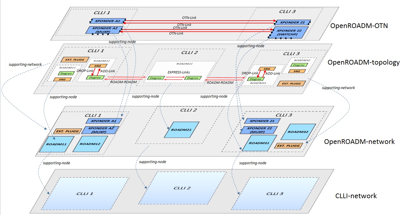
The topology is built retrieving information of all NETCONF Devices. ROADM to ROADM link are discovered using the lldp information embedded in the device (neighbors).
Topology management implementation
The topology is built dynamically as NETCONF OpenROADM nodes appear or disappear. As soon as the information to reach a NETCONF Node is provided to the controller, this last tries to establish a session with the corresponding node. If the connection is successful (connected status) the mounted node will be added automatically to the OpenRoadm topology through the Topology Management bundle. In this section we focus on the description of the main classes of the Topology Management bundle. Thus this description shall not be considered as exhaustive. It only provides information on the main building blocks of the Topology Management bundle, to clarify its purpose and give some high level details on its implementation.
NetworkModelprovider class, at initialization creates the different layers of the OpenROADM topology calling create<Clli / OpenRoadmNetwork / Topo>Layer methods NetconfTopologyListener class implements DataTreeChangeListener for the nodes. It defines several methods to handle all operations that shall be trigged when a new NETCONF OpenROADM node is connected/disconnected. OnDataTreeChanged method is overridden so that on a modification of a DataTree, corresponding LOG are produced, OndeviceConnected or OndeviceDisconnected methods are called. In the case a new device is connected, it also calls networkModelService.createOpenROADMNode method which will lead to the creation of the node at the level of the Topology. OnDeviceConnected method tries to get a mountpoint for the node, and instantiate all required listener : AlarmNotification, DeOperations, Device and TCA. It also launches RPC service for the node. OndeviceDisconnected removes node registration and close Listener registration services.
NetworkModelService.impl implements NetworkModelService interface and overrides createOpenROADMNode method. As explained above, this last is called when The NETCONF Topology listener detects a change in a DataTree for a specific node. It launches the creation of mapping data (mapping between device data such as Circuit-pack, ports… and abstracted data used by the Path Computation Engine as nodes, Logical connection points and links), and the creation of the node at the different level of the topology (CLLI, UNDERLAY, OVERLAY). It also calls R2RLink Discovery.readLLDP method to get information about identified lldp neighbors, and create the corresponding ROADM to ROADM link through createR2Rlink method.
ClliNetwork, OpenROADMNetwork and OpenROADMTopology are the three classes used to build the multi-layer topology. They are structured in the same way:
- a method create<Clli/OpenRoadmNetwork/Topo>Layer is used to create an object for the corresponding empty layer (CLLI, UNDERLAY & OVERLAY Layers, OTN layer will being addressed at a later step) in the MDSAL CONFIGURATION DataStore.
- a method create<Network/OpenRoadmNetwork/OpenRoadmTopology> is used to create an object for the corresponding empty network (CLLI, UNDERLAY & OVERLAY Networks, OTN network being addressed at a later step) in the MD-SAL CONFIGURATION DataStore.
- For CLLI and Underlay Network, a method createNode is used to create a single Node entry for the corresponding Network/layer. Information about the node are retrieved directly from the node DataStore using the DeviceTransactionManager. For overlay Network where we do not only separate Xponders from ROADM but where ROAD nodes are fully disaggregated, a method createTopologyShard is used to create all the elements corresponding to the disaggregated node in the MD-SAL CONFIGURATION DataStore. For ROADMs, this methods create all SRGs and Degrees, as well as all links interconnecting these disaggregated elements: express, add and drop links. For xpdr nodes, the method creates all required nodes. In the current implementation, only transponders nodes are created: as many nodes as client interfaces are created. Next implementation will address muxponders, and switchponders will be addressed at a later step. The method createTopologyShard relies on different methods to create the corresponding elements: createXpdr, createSrgNode, create DegreeNode, createExpressLinks and createAddDropLinks, which both rely on createLink. Additional methods are used to create the specific elements of the topology tree: ROADM’s TPs (TTPs, CTPs, CPs and PPS).
These Classes allow to initiate the different layers and to populate them with OpenROADM nodes. They are complemented by the classes handling Link discovery and creation, and are instanciated through NetworkModelServiceImpl.
R2RLinkDiscovery class is used to discover ROADM to ROADM links, from the lldp information stored in the nodes, and to populate the topology with this link (indirectly through the OrdLink class). It includes different utility methods that allow getting the degree, connection ports and their characteristics (uni/bi-directional) from the information of the interfaces (local/neighbor) embedded in the lldp info. The 3 main methods used to get lldp node information, and to create and delete ROADM to ROADM nodes are the following:
- readLLDP reads information related to lldp protocols in the devices. If a neighbor is present in the lldp tree, it calls another method to create the link from the node to the neighbor in the OVERLAY topology. If a neighbor has disappeared, it calls the another method to remove the link associated with a specific interface from the OVERLAY topology.
- createR2Rlink method, from information on A (local) and Z (remote or “neighbor”) nodes, checks the nature of the source and destination ports (uni/bi-directional) and a creates a Builder for the input of the RPC initRoadmNodes. Indeed, the creation of link in the OVERLAY topology involves two different processes: the link itself as existing between 2 operational nodes can be populated in the MD-SAL topology model from the information gathered through lldp protocol, but the OMS attributes includes some information that is not available in the device, but comes from external database (list of successive sections with corresponding cable/fiber-trunk, Shared Risk Link Groups, measured attenuations and PMD…). The OMS attributes is populated in the topology, through the REST Northbound interface, using the RPC initRoadmNodes.
- deleteR2Rlink method deletes from the OVERLAY topology in the CONFIGURATION Data Store the link from the node to neighbor.
OrdLink class includes the method createRdm2RdmLinks which creates a builder for the ROADM to ROADM link in the OVERLAY topology and post the new link in CONFIGURATION Data Store
Rdm2XpdrLink class includes the methods createXpdr2RdmLinks and createRdm2XpdrLinks which creates the links between ROADMs and Xponders in the OVERLAY topology (CONFIGURATION Data Store). They both rely on createNetworkBuilder method to create the builders. NetworkUtilsImpl publishes the different RPC associated with link creation. Link creation implies some actions from operational staff using RESTCONF northbound interface. For ROADM to ROADM link the OMS attributes must be entered to provide information about the structure of the OMS link and describe the succession of fiber/cables it is made of. As Xponders may be provisioned after the WDM infrastructure has been put in place, it is also necessary to populate the planned links in the topology database after the Xponders are in place .
The RPC initRoadmNodes, is used to create ROADM to ROADM links and populate the OMS attributes. The RPC initXpdrRdmLinks and initRdmXpdrlinks are used to create the XPONDER-ROADMs link that cannot be discovered through lldp. ....
Topology management initial requirements
To be completed
Device management
Device management description
Device management includes different submodules dedicated to fault, performances and configuration management. Thus it is responsible for building an inventory of the network elements, handling all the events associated to the NETCONF devices and storing their startup and running configurations in order to restore them in case of an event affecting a specific NE.
Whereas services' list and topology are maintained directly in the MD-SAL data store, Device key information, Alarms, PMs and configuration which represent a huge amount of data are stored in a specific SQL data base to avoid scalability issues.
Device management current implementation focuses on Alarm & PM management and device inventory. Configuration management has not been developed yet. The operation of the device management module implies that an SQL database is correctly installed, and set to host all the information provided by the module.
Alarm and PM management
____to be completed____
Inventory management
____to be completed____
Configuration management
____for later study____
Device management implementation
....
Device management initial requirements
To be completed
SQL database
This section provides details on the structure of the SQL database that shall be put in place in order to store all information related to NETCONF Open ROADM devices. Device management, through Alarm & PM management and Inventory management submodules fills and updates the database automatically. It also provides the procedure and the command to setup this database
Procedure to setup the initial SQL database
To be completed : commands and parameters used to setup the initial database
Structure of the SQL database dedicated to device management
Device information
To be completed
Alarms
To be completed
PMs
To be completed